Formeln

Saturday, March 23, 2013

The Camera Manager

In the last tutorial we saw, that with a growing number of cameras we need some additional code to manage different cameras. The reasons were: Renderables need access to the current camera, the different cameras share a set of variables and the handling of mouse and keyboard events is for each camera different.

The obvious way to address this problem is either by providing an interface or an abstract class. I chose an abstract class:

Abstract Class Camera


using System;
using System.Collections.Generic;
using System.Linq;
using System.Text;
using System.Windows.Forms;
using SlimDX;

namespace Apparat
{
    public abstract class Camera
    {
        public Vector3 eye;
        public Vector3 target;
        public Vector3 up;

        public Matrix view = Matrix.Identity;
        public Matrix perspective = Matrix.Identity;
        public Matrix viewPerspective = Matrix.Identity;

        public Matrix View
        {
            get { return view; }
        }

        public void setPerspective(float fov, float aspect, float znear, float zfar)
        {
            perspective = Matrix.PerspectiveFovLH(fov, aspect, znear, zfar);
        }

        public void setView(Vector3 eye, Vector3 target, Vector3 up)
        {
            view = Matrix.LookAtLH(eye, target, up);
        }

        public Matrix Perspective
        {
            get { return perspective; }
        }

        public Matrix ViewPerspective
        {
            get { return view * perspective; }
        }

        public bool dragging = false;
        public int startX = 0;
        public int deltaX = 0;

        public int startY = 0;
        public int deltaY = 0;

        public abstract void MouseUp(object sender, MouseEventArgs e);
        public abstract void MouseDown(object sender, MouseEventArgs e);
        public abstract void MouseMove(object sender, MouseEventArgs e);
        public abstract void MouseWheel(object sender, MouseEventArgs e);
    }
}

These are the variables and methods all cameras share. Furthermore cameras deriving from this abstract class have to implement the handlers for interacting with the control, like MouseUp. I deleted the corresponding variables and methods from the OrbitCamera and OrbitPanCamera classes did override the handlers. For the sake of brevity I will not post the code here but refer to the source code at the bottom of this tutorial.

CameraManager Class


using System;
using System.Collections.Generic;
using System.Linq;
using System.Text;

namespace Apparat
{
    public class CameraManager
    {
        #region Singleton Pattern
        private static CameraManager instance = null;
        public static CameraManager Instance
        {
            get
            {
                if (instance == null)
                {
                    instance = new CameraManager();
                }
                return instance;
            }
        }
        #endregion

        #region Constructor
        private CameraManager() 
        {
            OrbitPanCamera ocp = new OrbitPanCamera();
            OrbitCamera oc = new OrbitCamera();
            cameras.Add(ocp);
            cameras.Add(oc);

            currentIndex = 0;
            currentCamera = cameras[currentIndex];
        }
        #endregion

        List<camera> cameras = new List<camera>();

        public Camera currentCamera;
        int currentIndex;

        public string CycleCameras()
        {
            int numCameras = cameras.Count;
            currentIndex = currentIndex + 1;
            if (currentIndex == numCameras)
                currentIndex = 0;
            currentCamera = cameras[currentIndex];
            return currentCamera.ToString();
        }
    }
}

The CameraManager is now responsible for creating the cameras and uses the Singleton pattern, as it is the only object, the rest of the engine is talking to, when cameras need to be accessed. Consequently, the OrbitCamera and OrbitPanCamera are not Singletons anymore.

The CameraManager holds a list of cameras, which I populate in its contructor. In order to change the camera, I added the method CycleCameras. The engine can gain access to the current camera via the currentCamera variable with CameraManager.Instance.currentCamera.

RenderControl


using System;
using System.Collections.Generic;
using System.ComponentModel;
using System.Drawing;
using System.Data;
using System.Linq;
using System.Text;
using System.Windows.Forms;
using Apparat.Renderables;

namespace Apparat
{
    public partial class RenderControl : UserControl
    {
        public RenderControl()
        {
            InitializeComponent();
            this.MouseWheel += new MouseEventHandler(RenderControl_MouseWheel);
        }

        public void init()
        {
            DeviceManager.Instance.createDeviceAndSwapChain(this);
            RenderManager.Instance.init();

            Grid grid = new Grid(10, 1.0f);
            TriangleEF triangle = new TriangleEF();
            Scene.Instance.addRenderObject(triangle);
            Scene.Instance.addRenderObject(grid);
        }

        public void shutDown()
        {
            RenderManager.Instance.shutDown();
            DeviceManager.Instance.shutDown();
        }

        private void RenderControl_MouseUp(object sender, MouseEventArgs e)
        {
            CameraManager.Instance.currentCamera.MouseUp(sender, e);
        }

        private void RenderControl_MouseDown(object sender, MouseEventArgs e)
        {
            CameraManager.Instance.currentCamera.MouseDown(sender, e);
        }

        private void RenderControl_MouseMove(object sender, MouseEventArgs e)
        {
            CameraManager.Instance.currentCamera.MouseMove(sender, e);
        }

        void RenderControl_MouseWheel(object sender, MouseEventArgs e)
        {
            CameraManager.Instance.currentCamera.MouseWheel(sender, e);
        }

        private void RenderControl_KeyUp(object sender, KeyEventArgs e)
        {
            if (e.KeyCode == Keys.F1)
            {
                CameraManager.Instance.CycleCameras();
            }
        }
    }
}

In the RenderControl the mouse handlers refer to the current camera of the CameraManger and call
the according handler. Furthermore I use the KeyUp handler and the F1 key to cycle through the cameras.

Renderables

Now the render methods of the Renderables have to updated like in this example, where the ViewPerspective matrix is set via the CameraManager.

public override void render()
{
  Matrix ViewPerspective = CameraManager.Instance.currentCamera.ViewPerspective;
  tmat.SetMatrix(ViewPerspective);

  // configure the Input Assembler portion of the pipeline with the vertex data
  DeviceManager.Instance.context.InputAssembler.InputLayout = layout;
  DeviceManager.Instance.context.InputAssembler.PrimitiveTopology = PrimitiveTopology.LineList;
  DeviceManager.Instance.context.InputAssembler.SetVertexBuffers(0, new VertexBufferBinding(vertexBuffer, 12, 0));

  technique = effect.GetTechniqueByName("Render");

  EffectTechniqueDescription techDesc;
  techDesc = technique.Description;

  for (int p = 0; p < techDesc.PassCount; ++p)
  {
    technique.GetPassByIndex(p).Apply(DeviceManager.Instance.context);
    DeviceManager.Instance.context.Draw(numVertices, 0);
  }
}

Conclusion

When dealing with several cameras a CameraManager is needed to deal with them in a flexible way. This CameraManager will be extended in future tutorials. 

You can download the code for this tutorial here.

Friday, March 22, 2013

Orbit and Pan Camera

In the last tutorial I explained how to implement an Orbit Camera, with which you can circle around a given point. In this tutorial I will explain how to add the capability to pan. Panning means translating the camera parallel to the X-Z plane.

Source Code of the OrbitPanCamera


using System;
using System.Collections.Generic;
using System.Linq;
using System.Text;
using SlimDX;
using SlimDX.Direct3D11;
using SlimDX.DXGI;

namespace Apparat
{
    public class OrbitPanCamera
    {
        #region Singleton Pattern
        private static OrbitPanCamera instance = null;
        public static OrbitPanCamera Instance
        {
            get
            {
                if (instance == null)
                {
                    instance = new OrbitPanCamera();
                }
                return instance;
            }
        }
        #endregion

        #region Constructor
        private OrbitPanCamera()
        {
            eye = new Vector3(4, 2, 0);
            target = new Vector3(0, 0, 0);
            up = new Vector3(0, 1, 0);

            view = Matrix.LookAtLH(eye, target, up);
            perspective = Matrix.PerspectiveFovLH((float)Math.PI / 4, 1.3f, 0.0f, 1.0f);
        }
        #endregion

        Vector3 eye;
        Vector3 target;
        Vector3 up;

        Matrix view = Matrix.Identity;
        Matrix perspective = Matrix.Identity;
        Matrix viewPerspective = Matrix.Identity;

        public Matrix View
        {
            get { return view; }
        }

        public void setPerspective(float fov, float aspect, float znear, float zfar)
        {
            perspective = Matrix.PerspectiveFovLH(fov, aspect, znear, zfar);
        }

        public void setView(Vector3 eye, Vector3 target, Vector3 up)
        {
            view = Matrix.LookAtLH(eye, target, up);
        }

        public Matrix Perspective
        {
            get { return perspective; }
        }

        public Matrix ViewPerspective
        {
            get { return view * perspective; }
        }

        float rotY = 0;

        public void rotateY(int value)
        {
            rotY = (value / 100.0f);
            Vector3 eyeLocal = eye - target;

            Matrix rotMat = Matrix.RotationY(rotY);
            eyeLocal = Vector3.TransformCoordinate(eyeLocal, rotMat);
            eye = eyeLocal + target;

            setView(eye, target, up);
        }
        float rotOrtho = 0;

        public void rotateOrtho(int value)
        {
            Vector3 viewDir = target - eye;
            Vector3 orhto = Vector3.Cross(viewDir, up);
            
            rotOrtho = (value / 100.0f);
            Matrix rotOrthoMat = Matrix.RotationAxis(orhto, rotOrtho);

            Vector3 eyeLocal = eye - target;
            eyeLocal = Vector3.TransformCoordinate(eyeLocal, rotOrthoMat);
            Vector3 newEye = eyeLocal + target;
            Vector3 newViewDir = target - newEye;
            float cosAngle = Vector3.Dot(newViewDir, up) / (newViewDir.Length() * up.Length());
            if (cosAngle < 0.999f && cosAngle > -0.999f)
            {
               eye = eyeLocal + target;
               setView(eye, target, up);
            }
        }

        public void panX(int value)
        {
            float scaleFactor = 0.0f;
            if (value > 1)
            {
                scaleFactor = -0.05f;
            }
            else if (value < -1 )
            {
                scaleFactor = 0.05f;
            }
            Vector3 viewDir = target - eye;
            Vector3 orhto = Vector3.Cross(viewDir, up);
            orhto.Normalize();
            scaleFactor = scaleFactor * (float)Math.Sqrt(viewDir.Length()) * 0.5f;
            Matrix scaling = Matrix.Scaling(scaleFactor, scaleFactor, scaleFactor);
            orhto = Vector3.TransformCoordinate(orhto, scaling);
            
            target = target + orhto;
            eye = eye + orhto;
            setView(eye, target, up);
        }

        public void panY(int value)
        {
            float scaleFactor = 0.00f;
            if (value > 1)
            {
                scaleFactor = -0.05f;
            }
            else if (value < -1 )
            {
                scaleFactor = 0.05f;
            }
            Vector3 viewDir = target - eye;
            scaleFactor = scaleFactor * (float)Math.Sqrt(viewDir.Length()) * 0.5f;
            viewDir.Y = 0.0f;
            viewDir.Normalize();
            Matrix scaling = Matrix.Scaling(scaleFactor, scaleFactor, scaleFactor);
            viewDir = Vector3.TransformCoordinate(viewDir, scaling);

            target = target + viewDir;
            eye = eye + viewDir;
            setView(eye, target, up);
        }


        float maxZoom = 3.0f;
        public void zoom(int value)
        {
            Vector3 viewDir = eye - target;

            float scaleFactor = 1.0f;
            if (value > 0)
            {
                scaleFactor = 1.1f;
            }
            else
            {
                if (viewDir.Length() > maxZoom)
                    scaleFactor = 0.9f;
            }

            Matrix scale = Matrix.Scaling(scaleFactor, scaleFactor, scaleFactor);
            viewDir.Normalize();
            viewDir = Vector3.TransformCoordinate(viewDir, scale);
            if (value > 0)
            {
                eye = eye + viewDir;
            }
            else
            {
                eye = eye - viewDir;
            }
            
            setView(eye, target, up);
        }
    }
}

The source code for the OrbitPanCamera is in large parts the same as for the OrbitCamera. New are the methods for translating in the x-direction (Method panX) and translating in the y-direction (Method panY) of the screen.
Lets take a look at the panX Method:

public void panX(int value)
{
  float scaleFactor = 0.0f;
  if (value > 1)
  {
    scaleFactor = -0.05f;
  }
  else if (value < -1)
  {
    scaleFactor = 0.05f;
  }
  Vector3 viewDir = target - eye;
  Vector3 orhto = Vector3.Cross(viewDir, up);
  orhto.Normalize();
  scaleFactor = scaleFactor * (float)Math.Sqrt(viewDir.Length()) * 0.5f;
  Matrix scaling = Matrix.Scaling(scaleFactor, scaleFactor, scaleFactor);
  orhto = Vector3.TransformCoordinate(orhto, scaling);

  target = target + orhto;
  eye = eye + orhto;
  setView(eye, target, up);
}
The pose (position and orientation) is determined by the three vectors eye, target and up. The eye vector holds the current position of the camera, the target vector is the point to look at and the up vector defines the up direction. In order to pan sidewards, the general idea is to translate the position of the camera and the target to look at simultaneously. Therefore we calculate the direction we are looking (viewDir) and calculate the cross product with the up vector, which results in a vector that is pointing orthogonal to the viewDir vector.
This orthogonal vector is added to the target and eye vectors and we create a new view matrix, by calling setView. I perform scaling of the orthogonal vector depending in the distance to the target, so that the translation is little, if the camera is next to the target and bigger if the camera is far away.

The implementation of the panY method in analogue:
public void panY(int value)
{
  float scaleFactor = 0.00f;
  if (value > 1)
  {
    scaleFactor = -0.05f;
  }
  else if (value < -1)
  {
    scaleFactor = 0.05f;
  }
  Vector3 viewDir = target - eye;
  scaleFactor = scaleFactor * (float)Math.Sqrt(viewDir.Length()) * 0.5f;
  viewDir.Y = 0.0f;
  viewDir.Normalize();
  Matrix scaling = Matrix.Scaling(scaleFactor, scaleFactor, scaleFactor);
  viewDir = Vector3.TransformCoordinate(viewDir, scaling);

  target = target + viewDir;
  eye = eye + viewDir;
  setView(eye, target, up);
}
This time we don't need the orthogonal vector but only the view direction of the camera. Again this vector is scaled corresposing to the distance to the target and added to the target vector and eye vector of the camera. Like above, the new view matrix is created with this new values.

Adapting the Mouse Event Handlers of the RenderControl

The only handlers we have to adapt are RenderControl_MouseMove and RenderControl_MouseWheel.
These are the handlers of the OrbitCamera:


private void RenderControl_MouseMove(object sender, MouseEventArgs e)
{
  if (dragging)
  {
    int currentX = e.X;
    deltaX = startX - currentX;
    startX = currentX;

    int currentY = e.Y;
    deltaY = startY - currentY;
    startY = currentY;

    if (e.Button == System.Windows.Forms.MouseButtons.Left)
    {
      OrbitCamera.Instance.rotateY(-deltaX);
      OrbitCamera.Instance.rotateOrtho(deltaY);
    }
  }
}

void RenderControl_MouseWheel(object sender, MouseEventArgs e)
{
  int delta = e.Delta;
  OrbitCamera.Instance.zoom(delta);
}
We have to update the references from OrbitCamera to OrbitPanCamera and call the methods for panning in the RenderControl_MouseMove handler. I will use the right mouse button for panning:

private void RenderControl_MouseMove(object sender, MouseEventArgs e)
{
  if (dragging)
  {
    int currentX = e.X;
    deltaX = startX - currentX;
    startX = currentX;

    int currentY = e.Y;
    deltaY = startY - currentY;
    startY = currentY;

    if (e.Button == System.Windows.Forms.MouseButtons.Left)
    {
      OrbitPanCamera.Instance.rotateY(-deltaX);
      OrbitPanCamera.Instance.rotateOrtho(deltaY);
    }
    else if (e.Button == System.Windows.Forms.MouseButtons.Right)
    {
      OrbitPanCamera.Instance.panX(deltaX);
      OrbitPanCamera.Instance.panY(deltaY);
    }
  }
}

void RenderControl_MouseWheel(object sender, MouseEventArgs e)
{
  int delta = e.Delta;
  OrbitPanCamera.Instance.zoom(delta);
}

Adapting the Renderables

We are not quite done yet, because we need the ViewPerspective matrix of our OrbitPanCamera to set the transformation in our Renderables. I will omit the code for this here, because it is just replacing the references to OrbitCamera to OrbitPanCamera in the Renderable classes.

In order to make the handling of cameras more flexible, I will introduce a CameraManager in the next tutorial, so we can have several cameras and do not need to hardcode the handling of mouse events and switching of cameras in the Renderables.

Result


You can download the source code here.

Thursday, March 21, 2013

Orbit Camera

Requirements

An Orbit Camera is a camera that orbits around a given point. We have to consider two angles: azimuth and pitch. Usually you rotate in a horizontal fashion (azimuth) and in vertical (pitch). When rotating around the poles of the resulting sphere the camera is moving on, it is not preferred to go over the poles. Therefore we lock the camera at the poles and prohibit walking over the poles.

Walking over a pole would result in two unwanted behaviours, depending on the implementation: if the up vector of the camera switches its sign when transgressing the pole, this would result in looking from upside-down at the  scene. If the up vector keeps its sign while transgressing a pole, the view rotates instantaneously by 180° around the vertical axis, when wandering over the pole, which is uncomfortable to watch.

Rotating around the vertical axis is accomplished by moving the mouse right and left. Moving the mouse up and down results in a motion of the camera around the horizontal axis. The mouse wheel is for zooming in and out.

Source Code for the Orbit Camera

using System;
using System.Collections.Generic;
using System.Linq;
using System.Text;
using SlimDX;
using SlimDX.Direct3D11;
using SlimDX.DXGI;

namespace Apparat
{
    public class OrbitCamera
    {
        #region Singleton Pattern
        private static OrbitCamera instance = null;
        public static OrbitCamera Instance
        {
            get
            {
                if (instance == null)
                {
                    instance = new OrbitCamera();
                }
                return instance;
            }
        }
        #endregion

        #region Constructor
        private OrbitCamera()
        {
            eye = new Vector3(4, 2, 0);
            target = new Vector3(0, 0, 0);
            up = new Vector3(0, 1, 0);

            view = Matrix.LookAtLH(eye, target, up);
            perspective = Matrix.PerspectiveFovLH((float)Math.PI / 4, 1.3f, 0.0f, 1.0f);
        }
        #endregion

        Vector3 eye;
        Vector3 target;
        Vector3 up;

        Matrix view = Matrix.Identity;
        Matrix perspective = Matrix.Identity;
        Matrix viewPerspective = Matrix.Identity;

        public Matrix View
        {
            get { return view; }
        }

        public void setPerspective(float fov, float aspect, float znear, float zfar)
        {
            perspective = Matrix.PerspectiveFovLH(fov, aspect, znear, zfar);
        }

        public void setView(Vector3 eye, Vector3 target, Vector3 up)
        {
            view = Matrix.LookAtLH(eye, target, up);
        }

        public Matrix Perspective
        {
            get { return perspective; }
        }

        public Matrix ViewPerspective
        {
            get { return view * perspective; }
        }

        float rotY = 0;

        public void rotateY(int value)
        {
            rotY = (value / 100.0f);
            Matrix rotMat = Matrix.RotationY(rotY);
            eye = Vector3.TransformCoordinate(eye, rotMat);
            setView(eye, target, up);
        }
        float rotOrtho = 0;

        public void rotateOrtho(int value)
        {
            Vector3 viewDir = target - eye;
            Vector3 orhto = Vector3.Cross(viewDir, up);

            rotOrtho = (value / 100.0f);
            Matrix rotOrthoMat = Matrix.RotationAxis(orhto, rotOrtho);

            Vector3 eyeLocal = eye - target;
            eyeLocal = Vector3.TransformCoordinate(eyeLocal, rotOrthoMat);
            Vector3 newEye = eyeLocal + target;
            Vector3 newViewDir = target - newEye;
            float cosAngle = Vector3.Dot(newViewDir, up) / (newViewDir.Length() * up.Length());
            if (cosAngle < 0.9f && cosAngle > -0.9f)
            {
                eye = eyeLocal + target;
                setView(eye, target, up);
            }
        }


        float maxZoom = 3.0f;
        public void zoom(int value)
        {
            float scaleFactor = 1.0f;
            if (value > 0)
            {
                scaleFactor = 1.1f;
            }
            else
            {
                if ((eye - target).Length() > maxZoom)
                    scaleFactor = 0.9f;
            }

            Matrix scale = Matrix.Scaling(scaleFactor, scaleFactor, scaleFactor);
            eye = Vector3.TransformCoordinate(eye, scale);
            setView(eye, target, up);
        }
    }
}


The pose of the camera is defined by three vectors: up, eye and target. Up is a direction vector, that defines the up direction. Eye is the position of the camera and target is the position to look at. These vectors are set in the constructor of this class and are needed to create the look-at matrix, which we call view.

Here is the reference to the look at matrix:
http://slimdx.org/docs/html/M_SlimDX_Matrix_LookAtLH.htm
Every time, we change one of the three vectors up, eye or target, we call the setView method, in which we create a new view matrix.

Next we create the perspective matrix.
Reference: http://slimdx.org/docs/html/M_SlimDX_Matrix_PerspectiveFovLH.htm

The method rotateY is called, when moving the mouse left or right and preform a rotation around the y-axis.

The method rotateOrtho is called, when moving the mouse up or down. This method is named rotateOrtho, because the axis of rotation is orthogonal to up vector and the direction vector from the eye to the target. Here we also prevent the camera to transit the poles.

The zoom method is called, when using the mouse wheel.

Adapt the RenderControl

In order to control the camera with the mouse, we need to interact with the RenderControl. In order to do so, I handle four events:
  • MouseUp
  • MouseDown
  • MouseMove
  • MouseWheel

using System;
using System.Collections.Generic;
using System.ComponentModel;
using System.Drawing;
using System.Data;
using System.Linq;
using System.Text;
using System.Windows.Forms;
using Apparat.Renderables;

namespace Apparat
{
    public partial class RenderControl : UserControl
    {
        public RenderControl()
        {
            InitializeComponent();
            this.MouseWheel += new MouseEventHandler(RenderControl_MouseWheel);
        }

        public void init()
        {
            DeviceManager.Instance.createDeviceAndSwapChain(this);
            RenderManager.Instance.init();

            Grid grid = new Grid(10, 1.0f);
            TriangleEF triangle = new TriangleEF();
            Scene.Instance.addRenderObject(triangle);
            Scene.Instance.addRenderObject(grid);
        }

        public void shutDown()
        {
            RenderManager.Instance.shutDown();
            DeviceManager.Instance.shutDown();
        }

        public bool dragging = false;
        int startX = 0;
        int deltaX = 0;

        int startY = 0;
        int deltaY = 0;

        private void RenderControl_MouseUp(object sender, MouseEventArgs e)
        {
            dragging = false;
        }

        private void RenderControl_MouseDown(object sender, MouseEventArgs e)
        {
            dragging = true;
            startX = e.X;
            startY = e.Y;
        }

        private void RenderControl_MouseMove(object sender, MouseEventArgs e)
        {
            if (dragging)
            {
                int currentX = e.X;
                deltaX = startX - currentX;
                startX = currentX;

                int currentY = e.Y;
                deltaY = startY - currentY;
                startY = currentY;

                if (e.Button == System.Windows.Forms.MouseButtons.Left)
                {
                    OrbitCamera.Instance.rotateY(-deltaX);
                    OrbitCamera.Instance.rotateOrtho(deltaY);
                }
            }
        }

        void RenderControl_MouseWheel(object sender, MouseEventArgs e)
        {
            int delta = e.Delta;
            OrbitCamera.Instance.zoom(delta);
        }
    }
}

Adapt Renderables

The camera has a method called ViewPerspective, which return the result of a multiplication of the cameras view matrix with its perspective matrix. To set the according transformation in the renderables, this method has to be called in the render method of the renderables, e.g. the grid renderable:

public override void render()
{
  Matrix ViewPerspective = OrbitCamera.Instance.ViewPerspective;
  tmat.SetMatrix(ViewPerspective);

  // configure the Input Assembler portion of the pipeline with the vertex data
  DeviceManager.Instance.context.InputAssembler.InputLayout = layout;
  DeviceManager.Instance.context.InputAssembler.PrimitiveTopology = PrimitiveTopology.LineList;
  DeviceManager.Instance.context.InputAssembler.SetVertexBuffers(0, new VertexBufferBinding(vertexBuffer, 12, 0));

  technique = effect.GetTechniqueByName("Render");

  EffectTechniqueDescription techDesc;
  techDesc = technique.Description;

  for (int p = 0; p < techDesc.PassCount; ++p)
  {
    technique.GetPassByIndex(p).Apply(DeviceManager.Instance.context);
    DeviceManager.Instance.context.Draw(numVertices, 0);
  }
}

Here we get the ViewPerspective matrix from the camera and pass it to the Effect variable. The results can be seen in the videos below.

Results

This video shows how the camera rotates around the center of the global coordinate system. Because the transformations of the triangle were not adjusted to the transformation from the camera, the triangle still rotates in the middle of the window.

This video was made, after the transformation of the triangle was adapted. Now the triangle is stationary. Because the triangle is culled just from one side, it is invisible, if the camera is looking at it from the other side.

You can download the source code to this tutorial here.

Tuesday, March 19, 2013

Rendering a Grid with the LineList Primitive

In the next tutorials I am going to integrate a class for a camera. In order to have an orientation where we are going with the camera it is common to render a grid as reference.

Source Code of the Grid Renderable


using System;
using System.Collections.Generic;
using System.Linq;
using System.Text;
using SlimDX.D3DCompiler;
using SlimDX;
using SlimDX.Direct3D11;
using SlimDX.DXGI;

namespace Apparat.Renderables
{
    public class Grid : Renderable
    {
        SlimDX.Direct3D11.Buffer vertexBuffer;
        DataStream vertices;
        
        InputLayout layout;

        int numVertices = 0;

        ShaderSignature inputSignature;
        EffectTechnique technique;
        EffectPass pass;

        Effect effect;
        EffectMatrixVariable tmat;


        public Grid(int cellsPerSide, float cellSize)
        {
            try
            {
                using (ShaderBytecode effectByteCode = ShaderBytecode.CompileFromFile(
                    "transformEffectRasterizer.fx",
                    "Render",
                    "fx_5_0",
                    ShaderFlags.EnableStrictness,
                    EffectFlags.None))
                {
                    effect = new Effect(DeviceManager.Instance.device, effectByteCode);
                    technique = effect.GetTechniqueByIndex(0);
                    pass = technique.GetPassByIndex(0);
                    inputSignature = pass.Description.Signature;
                }
            }
            catch (Exception ex)
            {
                Console.WriteLine(ex.ToString());
            }

            tmat = effect.GetVariableByName("gWVP").AsMatrix();
          

            int numLines = cellsPerSide+1;
            float lineLength = cellsPerSide * cellSize;

            float xStart = -lineLength / 2.0f;
            float yStart = -lineLength / 2.0f;

            float xCurrent = xStart;
            float yCurrent = yStart;

            numVertices = 2 * 2 * numLines;
            int SizeInBytes = 12 * numVertices;

            vertices = new DataStream(SizeInBytes, true, true);

            for (int y = 0; y < numLines; y++)
            {
                vertices.Write(new Vector3(xCurrent, 0, yStart));
                vertices.Write(new Vector3(xCurrent, 0, yStart + lineLength));
                xCurrent += cellSize;
            }

            for (int x = 0; x < numLines; x++)
            {
                vertices.Write(new Vector3(xStart, 0, yCurrent));
                vertices.Write(new Vector3(xStart + lineLength, 0, yCurrent));
                yCurrent += cellSize;
            }

            vertices.Position = 0;

            // create the vertex layout and buffer
            var elements = new[] { new InputElement("POSITION", 0, Format.R32G32B32_Float, 0) };
            layout = new InputLayout(DeviceManager.Instance.device, inputSignature, elements);
            vertexBuffer = new SlimDX.Direct3D11.Buffer(DeviceManager.Instance.device, vertices, SizeInBytes, ResourceUsage.Default, BindFlags.VertexBuffer, CpuAccessFlags.None, ResourceOptionFlags.None, 0);
            

        }

        public override void render()
        {
            Matrix ViewPerspective = Matrix.Identity;

            tmat.SetMatrix(ViewPerspective);

            // configure the Input Assembler portion of the pipeline with the vertex data
            DeviceManager.Instance.context.InputAssembler.InputLayout = layout;
            DeviceManager.Instance.context.InputAssembler.PrimitiveTopology = PrimitiveTopology.LineList;
            DeviceManager.Instance.context.InputAssembler.SetVertexBuffers(0, new VertexBufferBinding(vertexBuffer, 12, 0));

            technique = effect.GetTechniqueByName("Render");

            EffectTechniqueDescription techDesc;
            techDesc = technique.Description;

            for (int p = 0; p < techDesc.PassCount; ++p)
            {
                technique.GetPassByIndex(p).Apply(DeviceManager.Instance.context);
                DeviceManager.Instance.context.Draw(numVertices, 0);
            }
            
        }

        public override void dispose()
        {
            inputSignature.Dispose();
        }
    }
}

The constructor of the grid takes the number of cells per side and the cell size as arguments. In the constructor the vertices of the grid are created. I have arranged the grid in a way, that the center of the grid
corresponds with the origin of the grids local coordinate system. If you compare this code to the code for the  triangle used in the previous tutorial, only the creation of the vertices differs.

The Render Method

This is the render method of the triangle of the last tutorial. The transformation matrix of the triangle is set via the Effect Framework.

public override void render()
{
  rot += 0.01f;
  rotMat = Matrix.RotationY(rot);
  tmat.SetMatrix(Matrix.Transpose(rotMat));

  // configure the Input Assembler portion of the pipeline with the vertex data
  DeviceManager.Instance.context.InputAssembler.InputLayout = layout;
  DeviceManager.Instance.context.InputAssembler.PrimitiveTopology = PrimitiveTopology.TriangleList;
  DeviceManager.Instance.context.InputAssembler.SetVertexBuffers(0, new VertexBufferBinding(vertexBuffer, 12, 0));

  technique = effect.GetTechniqueByName("Render");

  EffectTechniqueDescription techDesc;
  techDesc = technique.Description;

  for (int p = 0; p < techDesc.PassCount; ++p)
  {
    technique.GetPassByIndex(p).Apply(DeviceManager.Instance.context);
    DeviceManager.Instance.context.Draw(3, 0);
  }
}

Compare this to the render method of the grid:

public override void render()
{
  Matrix ViewPerspective = Matrix.Identity;

  tmat.SetMatrix(ViewPerspective);

  // configure the Input Assembler portion of the pipeline with the vertex data
  DeviceManager.Instance.context.InputAssembler.InputLayout = layout;
  DeviceManager.Instance.context.InputAssembler.PrimitiveTopology = PrimitiveTopology.LineList;
  DeviceManager.Instance.context.InputAssembler.SetVertexBuffers(0, new VertexBufferBinding(vertexBuffer, 12, 0));

  technique = effect.GetTechniqueByName("Render");

  EffectTechniqueDescription techDesc;
  techDesc = technique.Description;

  for (int p = 0; p < techDesc.PassCount; ++p)
  {
    technique.GetPassByIndex(p).Apply(DeviceManager.Instance.context);
    DeviceManager.Instance.context.Draw(numVertices, 0);
  }
}
Here the transformation matrix, called ViewPerspective is set to the Identity Matrix, resulting in no transformation. This is the point, where the transformation from the camera will come into play in the next tutorial.

While we could call in the triangle class the Draw method with 3 vertices, we have to use for the grid class a variable called numVertices, as the vertices of the lines are created in the constructor and depend on the number of cells of our grid.

The next thing to note is that the primitive typology for the triangle was PrimitiveTopology.TriangleList and in the primitive typology for the grid is PrimitiveTopology.LineList.

The reference to the SlimDX Primitive Topology Enumeration is here:
http://slimdx.org/docs/html/T_SlimDX_Direct3D11_PrimitiveTopology.htm

The most common primitives are:

  • PointList
  • LineList
  • LineStrip
  • TriangleList
  • TriangleStrip
We have used the LineList and the TriangleList so far.

Result

So far, we get the following picture, when compiling and executing the code:


The result is quite sobering, as we just see an additional line in the center of the window. This is because, the view is aligned with the horizontal plane and we see the grid from the side.
You can try to rotate the grid programmatically like in the triangle class. Hint:  Matrix.RotationX(float angle) is your friend.
In the next tutorial I will introduce an Orbit Camera, that allows you to zoom and rotate around the origin of the global coordinate system.

You can download the source code to this tutorial here.

Setting Transformations in a Shader with the Effect Framework

In the previous tutorial I showed how to set a transformation in a shader via a Contant Buffer, resulting
in a rotating triangle. In this tutorial I will implement the same functionality with the Effect Framework.

Triangle Source Code


using System;
using System.Collections.Generic;
using System.Linq;
using System.Text;
using SlimDX.D3DCompiler;
using SlimDX;
using SlimDX.Direct3D11;
using SlimDX.DXGI;

namespace Apparat.Renderables
{
    public class TriangleEF : Renderable
    {
        ShaderSignature inputSignature;
        EffectTechnique technique;
        EffectPass pass;

        Effect effect;

        InputLayout layout;
        SlimDX.Direct3D11.Buffer vertexBuffer;

        EffectMatrixVariable tmat;

        public TriangleEF()
        {
            try
            {
                using (ShaderBytecode effectByteCode = ShaderBytecode.CompileFromFile(
                    "transformEffect.fx",
                    "Render",
                    "fx_5_0",
                    ShaderFlags.EnableStrictness,
                    EffectFlags.None))
                {
                    effect = new Effect(DeviceManager.Instance.device, effectByteCode);
                    technique = effect.GetTechniqueByIndex(0);
                    pass = technique.GetPassByIndex(0);
                    inputSignature = pass.Description.Signature;
                }
            }
            catch (Exception ex)
            {
                Console.WriteLine(ex.ToString());
            }

            tmat = effect.GetVariableByName("gWVP").AsMatrix();

            // create test vertex data, making sure to rewind the stream afterward
            var vertices = new DataStream(12 * 3, true, true);
            vertices.Write(new Vector3(0.0f, 0.5f, 0.5f));
            vertices.Write(new Vector3(0.5f, -0.5f, 0.5f));
            vertices.Write(new Vector3(-0.5f, -0.5f, 0.5f));
            vertices.Position = 0;

            // create the vertex layout and buffer
            var elements = new[] { new InputElement("POSITION", 0, Format.R32G32B32_Float, 0) };
            layout = new InputLayout(DeviceManager.Instance.device, inputSignature, elements);
            vertexBuffer = new SlimDX.Direct3D11.Buffer(
                DeviceManager.Instance.device,
                vertices,
                12 * 3,
                ResourceUsage.Default,
                BindFlags.VertexBuffer,
                CpuAccessFlags.None,
                ResourceOptionFlags.None,
                0);
        }

        public override void dispose()
        {
            effect.Dispose();
            inputSignature.Dispose();
            vertexBuffer.Dispose();
            layout.Dispose();
        }

        float rot = 0.0f;
        Matrix rotMat;

        public override void render()
        {
            rot += 0.01f;
            rotMat = Matrix.RotationY(rot);
            tmat.SetMatrix(rotMat);
           
            // configure the Input Assembler portion of the pipeline with the vertex data
            DeviceManager.Instance.context.InputAssembler.InputLayout = layout;
            DeviceManager.Instance.context.InputAssembler.PrimitiveTopology = PrimitiveTopology.TriangleList;
            DeviceManager.Instance.context.InputAssembler.SetVertexBuffers(0, new VertexBufferBinding(vertexBuffer, 12, 0));
            
            technique = effect.GetTechniqueByName("Render");

            EffectTechniqueDescription techDesc;
            techDesc = technique.Description;

            for (int p = 0; p < techDesc.PassCount; ++p)
            {
                technique.GetPassByIndex(p).Apply(DeviceManager.Instance.context);
                DeviceManager.Instance.context.Draw(3, 0);
            }
        }
    }
}

Shader Source Code


matrix gWVP;

float4 VShader(float4 position : POSITION) : SV_POSITION
{
 return mul( position, gWVP);
}

float4 PShader(float4 position : SV_POSITION) : SV_Target
{
 return float4(0.0f, 0.0f, 1.0f, 1.0f);
}

technique10 Render
{
 pass P0
 {
  SetVertexShader( CompileShader( vs_4_0, VShader() ));
  SetGeometryShader( NULL );
  SetPixelShader( CompileShader( ps_4_0, PShader() ));
 }
}

Explaining the Shader Source Code

In contrast to the previous shader in the last tutorial I do not declare the matrix variable gWVP in a
ConstantBuffer but directly as a matrix.

Also. when using the Effect Framework you have to define a Technique with at least one Pass:


technique10 Render
{
 pass P0
 {
  SetVertexShader( CompileShader( vs_4_0, VShader() ));
  SetGeometryShader( NULL );
  SetPixelShader( CompileShader( ps_4_0, PShader() ));
 }
}

The Technique is your interface to your shader from your code and in the Pass the shaders are set. I will explain in the next section how to interface with your shader.

Explaining the Triangle Source Code

In the last tutorial you had to load the VertexShader and the PixelShader seperately. With the Effect Framework you just have to load the ShaderBytecode for the effect:

try
{
  using (ShaderBytecode effectByteCode = ShaderBytecode.CompileFromFile(
    "transformEffect.fx",
    "Render",
    "fx_5_0",
    ShaderFlags.EnableStrictness,
    EffectFlags.None))
  {
    effect = new Effect(DeviceManager.Instance.device, effectByteCode);
    technique = effect.GetTechniqueByIndex(0);
    pass = technique.GetPassByIndex(0);
    inputSignature = pass.Description.Signature;
  }
}
catch (Exception ex)
{
  Console.WriteLine(ex.ToString());
}

tmat = effect.GetVariableByName("gWVP").AsMatrix();

When compiling the ShaderBytecode you have to set the name of the Technique as a parameter, in this case "Render". You have to create the effect by calling the constructor of the Effect Class with the device and the ShaderBytecode as parameters. Also you have access the technique and pass to get the InputSignature of the shader.

In order to access the matrix variable in your shader, you have to use the getVariableByName function of the effect. The matrix from the effect file is asigned to a matrix called tmat, which is of the type EffectMatrixVariable. We will use the variable tmat again in the render function of the triangle to set the transformation of the triangle:

public override void render()
{
  rot += 0.01f;
  rotMat = Matrix.RotationY(rot);
  tmat.SetMatrix(rotMat);
           
  // configure the Input Assembler portion of the pipeline with the vertex data
  DeviceManager.Instance.context.InputAssembler.InputLayout = layout;
  DeviceManager.Instance.context.InputAssembler.PrimitiveTopology = PrimitiveTopology.TriangleList;
  DeviceManager.Instance.context.InputAssembler.SetVertexBuffers(0, new VertexBufferBinding(vertexBuffer, 12, 0));
            
  technique = effect.GetTechniqueByName("Render");

  EffectTechniqueDescription techDesc;
  techDesc = technique.Description;

  for (int p = 0; p < techDesc.PassCount; ++p)
  {
    technique.GetPassByIndex(p).Apply(DeviceManager.Instance.context);
    DeviceManager.Instance.context.Draw(3, 0);
  }
}

The statement tmat.SetMatrix(rotMat) sets the variable for the transformation matrix in the effect.

Now we get a rotating triangle again:


Observe, that the triangle is rotating counter-clockwise, while the triangle in the previous tutorial was rotating clockwise. As far as i know, DirectX uses per default a left-handed coordinate system and the triangle should rotate clockwise with positively growing values for rotation around the y-axis. This can be resolved by transposing the matrix before passing it to the Effect Framework: tmat.SetMatrix(Matrix.Transpose(rotMat)) and the triangle is rotating clockwise again.

You can download the source code here.


Saturday, November 10, 2012

Setting Transformations in a Shader with a Constant Buffer

In this tutorial I will show you, how you can set Transformations in a Shader via the Constant Buffer.
We will render a Triangle and perform a rotation on it while rendering.

Triangle Source Code


using System;
using System.Collections.Generic;
using System.Linq;
using System.Text;
using SlimDX.D3DCompiler;
using SlimDX;
using SlimDX.Direct3D11;
using SlimDX.DXGI;

namespace Apparat.Renderables
{
    public class TriangleCB : Renderable
    {
        ShaderSignature inputSignature;
        VertexShader vertexShader;
        PixelShader pixelShader;

        InputLayout layout;
        SlimDX.Direct3D11.Buffer vertexBuffer;

        public TriangleCB()  
        {

            #region shader and triangle

            try
            {
                // load and compile the vertex shader
                using (var bytecode = ShaderBytecode.CompileFromFile("transform.fx", "VShader", "vs_4_0", ShaderFlags.None, EffectFlags.None))
                {
                    inputSignature = ShaderSignature.GetInputSignature(bytecode);
                    vertexShader = new VertexShader(DeviceManager.Instance.device, bytecode);
                }
            }
            catch (Exception ex)
            {
                Console.WriteLine(ex.ToString());
            }

            // load and compile the pixel shader
            using (var bytecode = ShaderBytecode.CompileFromFile("transform.fx", "PShader", "ps_4_0", ShaderFlags.None, EffectFlags.None))
            {
                pixelShader = new PixelShader(DeviceManager.Instance.device, bytecode);
            }

            // create test vertex data, making sure to rewind the stream afterward
            var vertices = new DataStream(12 * 3, true, true);
            vertices.Write(new Vector3(0.0f, 0.5f, 0.5f));
            vertices.Write(new Vector3(0.5f, -0.5f, 0.5f));
            vertices.Write(new Vector3(-0.5f, -0.5f, 0.5f));
            vertices.Position = 0;

            // create the vertex layout and buffer
            var elements = new[] { new InputElement("POSITION", 0, Format.R32G32B32_Float, 0) };
            layout = new InputLayout(DeviceManager.Instance.device, inputSignature, elements);
            vertexBuffer = new SlimDX.Direct3D11.Buffer(
                DeviceManager.Instance.device,
                vertices,
                12 * 3,
                ResourceUsage.Default,
                BindFlags.VertexBuffer,
                CpuAccessFlags.None,
                ResourceOptionFlags.None,
                0);
            #endregion
        }

        public override void dispose()
        {
            pixelShader.Dispose();
            vertexShader.Dispose();
            inputSignature.Dispose();
        }

        float rot = 0.0f;
        Matrix rotMat; 

        public override void render()
        {
            rot += 0.01f;
            rotMat = Matrix.RotationY(rot);

            var matStream = new DataStream(64, true, true);
            matStream.Write(rotMat);
            matStream.Position = 0;

            using (SlimDX.Direct3D11.Buffer matBuffer = new SlimDX.Direct3D11.Buffer(DeviceManager.Instance.device,     //Device
                                                             matStream, //Stream
                                                             64,         // Size                
                                                                // Flags
                                                             ResourceUsage.Dynamic,
                                                             BindFlags.ConstantBuffer,
                                                             CpuAccessFlags.Write,
                                                             ResourceOptionFlags.None,
                                                             4))
            {
                DeviceManager.Instance.context.VertexShader.SetConstantBuffer(matBuffer, 0);
            }


            // configure the Input Assembler portion of the pipeline with the vertex data
            DeviceManager.Instance.context.InputAssembler.InputLayout = layout;
            DeviceManager.Instance.context.InputAssembler.PrimitiveTopology = PrimitiveTopology.TriangleList;
            DeviceManager.Instance.context.InputAssembler.SetVertexBuffers(0, new VertexBufferBinding(vertexBuffer, 12, 0));

            //// set the shaders
            DeviceManager.Instance.context.VertexShader.Set(vertexShader);
            DeviceManager.Instance.context.PixelShader.Set(pixelShader);

            // render the triangle
            DeviceManager.Instance.context.Draw(3, 0);
        }


    }
}

Shader Source Code


cbuffer ConstBuffer : register(c0)
{
 float4x4 gWVP;
}

float4 VShader(float4 position : POSITION) : SV_POSITION
{
 return mul( position, gWVP);
}

float4 PShader(float4 position : SV_POSITION) : SV_Target
{
 return float4(1.0f, 0.0f, 0.0f, 1.0f);
}

Explanation of the Shader Source Code

In order to set transformations, we need to have a variable in the Shader to assign the transformation.
In this shader I call the variable gWVP and it is declared in the ConstantBuffer:


cbuffer ConstBuffer : register(c0)
{
 float4x4 gWVP;
}


To apply the transformation to each vertex of our triangle, we have to apply a Multiplication with
the Transformation Matrix.

float4 VShader(float4 position : POSITION) : SV_POSITION
{
 return mul( position, gWVP);
}


Explanation of the Triangle Source Code

If you compare the Constructor of the TriangleCB class above with the Constructor of the Triangle class
in the "Rendering a Triangle" Tutorial, everything remains the same:

We create a VertexShader, a Pixel Shader, we write the Vertices of the Triangle to a DataStream and create a VertexBuffer.

I added two Variables for the rotation of the Triangle and a Matrix to hold the Transformation Matrix:


float rot = 0.0f;
Matrix rotMat; 

The interesting part happens in the render Function of our Triangle. Let's have a short look at our original Version of our Triangle:

public override void render()
{
  // configure the Input Assembler portion of the pipeline with the vertex data
  DeviceManager.Instance.context.InputAssembler.InputLayout = layout;
  DeviceManager.Instance.context.InputAssembler.PrimitiveTopology = PrimitiveTopology.TriangleList;
  DeviceManager.Instance.context.InputAssembler.SetVertexBuffers(0, new VertexBufferBinding(vertexBuffer, 12, 0));

  // set the shaders
  DeviceManager.Instance.context.VertexShader.Set(vertexShader);
  DeviceManager.Instance.context.PixelShader.Set(pixelShader);

  // render the triangle
  DeviceManager.Instance.context.Draw(3, 0);
}

The Input Assembler Stage is set with an InputLayout, we provide a Primitive Topology and the Vertex Buffer is set. The Vertex and Pixel Shader are set in the Device and we can finally draw the Triangle.

Our new render function looks like this:


public override void render()
{
  rot += 0.01f;
  rotMat = Matrix.RotationY(rot);

  var matStream = new DataStream(64, true, true);
  matStream.Write(rotMat);
  matStream.Position = 0;

  using (SlimDX.Direct3D11.Buffer matBuffer = new SlimDX.Direct3D11.Buffer(
    DeviceManager.Instance.device,     //Device
    matStream, //Stream
    64,         // Size                
    // Flags
    ResourceUsage.Dynamic,
    BindFlags.ConstantBuffer,
    CpuAccessFlags.Write,
    ResourceOptionFlags.None,
    4)){             DeviceManager.Instance.context.VertexShader.SetConstantBuffer(matBuffer, 0);
  }

  // configure the Input Assembler portion of the pipeline with the vertex data
  DeviceManager.Instance.context.InputAssembler.InputLayout = layout;
  DeviceManager.Instance.context.InputAssembler.PrimitiveTopology = PrimitiveTopology.TriangleList;
  DeviceManager.Instance.context.InputAssembler.SetVertexBuffers(0, new VertexBufferBinding(vertexBuffer, 12, 0));

  // set the shaders
  DeviceManager.Instance.context.VertexShader.Set(vertexShader);
  DeviceManager.Instance.context.PixelShader.Set(pixelShader);

  // render the triangle
  DeviceManager.Instance.context.Draw(3, 0);
}

The lower part of the Source Code is exactly the same. In the upper part I add 0.01f of rotation in every frame. Then this rotation value is used to create a Rotation Matrix, that performs a Rotation around the Y-Axis:

rot += 0.01f;
rotMat = Matrix.RotationY(rot);

Next I create a DataStream, to write the Rotation Matrix to:

var matStream = new DataStream(64, true, true);
matStream.Write(rotMat);
matStream.Position = 0;

The SlimDX DataStream Class has the following Constructor:

public DataStream(long sizeInBytes, bool canRead, bool canWrite);

So when creating the DataStream the Size of the Matrix in Bytes has to be given as a Parameter.
A Matrix is a struct with 4x4 float, a float consists of 4 Bytes, so the Matrix struct has the size of 64 Bytes, thus we have to create the DataStream with a size of 64 Bytes. And we assign the Matrix rotMat by writing it to the stream. Finally we have to rewind the Stream by setting its Position to 0.

Finally we have to assign the Transformation Matrix to the VertexShader:

using (SlimDX.Direct3D11.Buffer matBuffer = new SlimDX.Direct3D11.Buffer(DeviceManager.Instance.device, //Device
  matStream, //Stream
  64,        // Size                
  // Flags
  ResourceUsage.Dynamic,
  BindFlags.ConstantBuffer,
  CpuAccessFlags.Write,
  ResourceOptionFlags.None,
  4))
{
  DeviceManager.Instance.context.VertexShader.SetConstantBuffer(matBuffer, 0);
}

This is done by creating a Buffer that holds the DataStream with the Data of the Rotation Matrix. Then we use this Buffer to set the ConstantBuffer of the VertexShader.

When Creating the Triangle, adding it to the Scene and let the Program run, you a get a rotating red Triangle:


You can download the Project here:
http://apparat.codeplex.com/SourceControl/changeset/9d048db48302

Sunday, November 4, 2012

Creating a UserControl for the Render Engine

In this tutorial I will show you, how you can create a User Control that you can add to new projects just by dragging and dropping it from your toolbox to your form.

Adding a UserControl


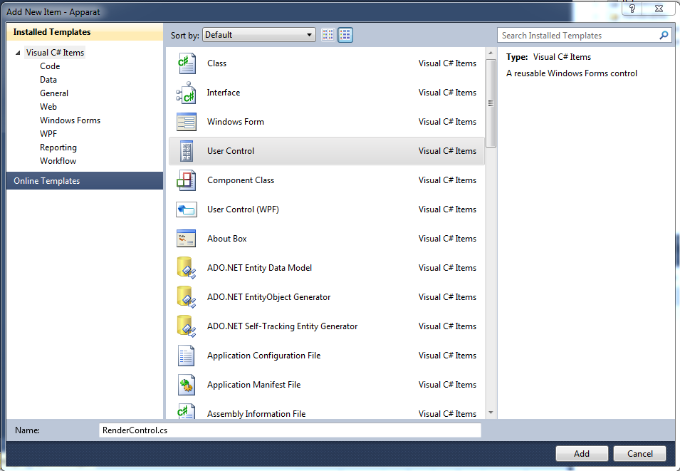
Start by Right-Clicking on your Apparat Project and select Add/UserControl:


In the following Dialogue select User Control. I will name this Control RenderControl. To add the Control, click Add on the right bottom of the Dialogue:


Functions in the UserControl

Let's take a look at our class Form1 in the MDX11Form Project:


namespace MDX11Form
{
    public partial class Form1 : Form
    {
        public Form1()
        {
            InitializeComponent();
            DeviceManager.Instance.createDeviceAndSwapChain(this);
            RenderManager.Instance.init();

            Triangle triangle = new Triangle();
            Scene.Instance.addRenderObject(triangle);
        }

        public void shutDown()
        {
            RenderManager.Instance.shutDown();
            DeviceManager.Instance.shutDown();
        }

        private void Form1_FormClosing(object sender, FormClosingEventArgs e)
        {
            shutDown();
        }
    }
}


Observe, that the function createDeviceAndSwapChain has the following signature:
public void createDeviceAndSwapChain(System.Windows.Forms.Control form)

All User Controls inherit from System.Windows.Controls.Control and we can reuse this code
in our RenderControl. Furthermore I move the shutDown Method into the User Control.
To edit the RenderControl Right-Click on it in the Apparat-Project and select View Code.

Visual Studio created the following Code for us, when we added the User Control:


namespace Apparat
{
    public partial class RenderControl : UserControl
    {
        public RenderControl()
        {
            InitializeComponent();
        }
    }
}

Copying the above mentioned code, and moving the code to create the DeviceManager and RenderManager to an init function, the code in our RenderControl now looks like this:


using System;
using System.Collections.Generic;
using System.ComponentModel;
using System.Drawing;
using System.Data;
using System.Linq;
using System.Text;
using System.Windows.Forms;
using Apparat.Renderables;

namespace Apparat
{
    public partial class RenderControl : UserControl
    {
        public RenderControl()
        {
            InitializeComponent();
           
        }

        public void init()
        {
            DeviceManager.Instance.createDeviceAndSwapChain(this);
            RenderManager.Instance.init();

            Triangle triangle = new Triangle();
            Scene.Instance.addRenderObject(triangle);
        }

        public void shutDown()
        {
            RenderManager.Instance.shutDown();
            DeviceManager.Instance.shutDown();
        }
    }
}

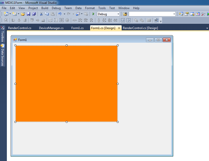
In order to make the RenderControl visible, when I drag it to a Form, I set the BackColor of the
RenderControl to Orange in the Properties of the RenderControl.
And we are done with the User Control!
At this stage you have to Rebuild the Apparat Library.

Adding the RenderControl to the Form

Now Double-Click the Form1 in the MDX11Form Project. If you select the Toolbox of Visual Studio,
the RenderControl shows up in our Toolbox:


Click the RenderControl in the Toolbox and click somewhere in the Form1 to drop our RenderControl there, or you can use Drag&Drop from the Toolbox. Adjusting the sizes of the Form1 and the RenderControl, the Form1 looks now like this:


If your compile the MDX11Form Project right now, you see nothing but the orange rectangle in the Form1.
Double-Click in the Designer on the Form1 to edit the Handler for the Load event of the Form.
Visual Studio created a renderControl1 object of our RenderControl, when we added it to the Form.
We can access the functions via this renderControl1 object.

All you have to do, to get the RenderControl working, is to call its init function. I do it in the Handler
of the Load event. To shut down, properly, I call the shutDown Method in the Handler of the FormClosing event:

using System;
using System.Collections.Generic;
using System.ComponentModel;
using System.Data;
using System.Drawing;
using System.Linq;
using System.Text;
using System.Windows.Forms;
using Apparat;
using Apparat.Renderables;

namespace MDX11Form
{
    public partial class Form1 : Form
    {
        public Form1()
        {
            InitializeComponent();
        }

        private void Form1_FormClosing(object sender, FormClosingEventArgs e)
        {
            renderControl1.shutDown();
        }

        private void Form1_Load(object sender, EventArgs e)
        {
            renderControl1.init();
        }
    }
}

If you start the Solution now, you can see that our Render Engine is running in our UserControl:


You can download the Solution here:
http://apparat.codeplex.com/SourceControl/changeset/dc772f719b14