Formeln

Wednesday, April 17, 2013

Rendering a Wireframe over a Mesh

This tutorial is one part of a series of tutorials about generating procedural meshes. See here for an outline.

Rendering a wireframe over a given mesh is relatively simple and requires just a second pass in the shader and two states for the rasterizer.

So far we used an effect technique with one pass:

technique10 Render
{
  pass P0
  {
    SetVertexShader( CompileShader( vs_4_0, VShader() ));
    SetGeometryShader( NULL );
    SetPixelShader( CompileShader( ps_4_0, PShader() ));
  }
}


This is the shader code for rendering the wireframe over the mesh:


matrix gWVP;
float4 wireFrameColor;

struct VOut
{
  float4 position : SV_POSITION;
  float4 color : COLOR;
};

VOut VShader(float4 position : POSITION, float4 color : COLOR)
{
  VOut output;

  output.position = mul( position, gWVP);
  output.color = color;

  return output;
}

float4 PShader(float4 position : SV_POSITION, float4 color : COLOR) : SV_TARGET
{
  return color;
}

float4 PShaderWireframe(float4 position : SV_POSITION, float4 color : COLOR) : SV_TARGET
{
  return wireFrameColor;
}

RasterizerState WireframeState
{
  FillMode = Wireframe;
};

RasterizerState SolidState
{
  FillMode = Solid;
};

technique10 Render
{
  pass P0
  {
    SetVertexShader( CompileShader( vs_4_0, VShader() ));
    SetGeometryShader( NULL );
    SetPixelShader( CompileShader( ps_4_0, PShader() ));
    SetRasterizerState(SolidState);
  }

  pass P1
  {
    SetVertexShader( CompileShader( vs_4_0, VShader() ));
    SetGeometryShader( NULL );
    SetPixelShader( CompileShader( ps_4_0, PShaderWireframe() ));
    SetRasterizerState(WireframeState);
  }
}

In the first pass P0 I set the fillmode state to Solid, to render the mesh. In the second pass P1 the fillmode state is set to Wireframe. Observe, that while I use in P0 and P1 the same vertex shader (which is kind of obious, because the wireframe needs the same transformations as the solid mesh), but use a different pixel shader, called PShaderWireframe. In this second pixel shader I set the color of the wireframe pixels to the variable wireFrameColor, to render the wireframe in a given color.

The variable wireFrameColor is set via the effect framework in the renderable object. This way there is no need to recompile the shader in case I want to use a different color for the wireframe.

In the code for the renderable I have to declare a variable of the type EffectVectorVariable:

EffectVectorVariable wireFrameColor;

This variable is bound to the shader variable in the constructor of the renderable object with this statement:

wireFrameColor = effect.GetVariableByName("wireFrameColor").AsVector();
Vector4 col = new Vector4(0, 0, 0, 1);
wireFrameColor.Set(col);

I just need to set this variable once in the constructor. If you want to do things like changing the color at runtime, you need to put the asignment wireFrameColor.Set(col) into the render method to make sure, it gets called in every frame.

Result


You can download the source code for this tutorial here.

The Color Cube: Vertices with Color

This tutorial is one part of a series of tutorials about generating procedural meshes. See here for an outline.

Vertices

So far I used simple vertices with only information about position in it. The vertex buffer consisted of an array of Vector3 structs. As I mentioned earlier, vertices can be more complex objects, holding further information about color, normals, texture coordinates and so on. In previous tutorials I used the pixel shader and hardcoded the color of the the pixel of an object:

float4 PShader(float4 position : SV_POSITION) : SV_Target
{
  return float4(0.0f, 1.0f, 0.0f, 1.0f);
}

This simple pixel shader just colors every of an object lime green, as the first three values of the float4 struct correspond to the RGB color model (standing for red, greed, blue).

First, we need a vertex structure, that can hold additional information about color:

[StructLayout(LayoutKind.Sequential)]
public struct Vertex
{
  public Vector3 Position;
  public int Color;

  public Vertex(Vector3 position, int color)
  {
    this.Position = position;
    this.Color = color;
  }
}

From here on we need to create a DataStream and write new vertices to this stream like in this statement:

vertices.Write(new Vertex(new Vector3(1.0f, 1.0f, 1.0f), Color.FromArgb(255, 0, 0).ToArgb()));

We create a new vertex at position x = 1, y = 1 and z = 1 and we tell the Color struct that we want the color red.

We are not done yet. The vertex buffer is just a stream of bytes and we need to tell our device how to interpret this data. This is exactly was the InputLayout is made for.
In previous tutorials I used this InputLayout:

var elements = new[] { new InputElement("POSITION", 0, Format.R32G32B32_Float, 0) };
layout = new InputLayout(DeviceManager.Instance.device, inputSignature, elements);

The InputLayout needs an array of InputElements. The InputElement array so far just consisted of the one element defined above, holding only information about the position. So we need to add a further InputElement for color:

var elements = new[] { 
  new InputElement("POSITION", 0, Format.R32G32B32_Float, 0),
  new InputElement("COLOR", 0, Format.B8G8R8A8_UNorm, 12, 0) 
};
layout = new InputLayout(DeviceManager.Instance.device, inputSignature, elements);

The second InputElement for color also gives information about its offset from the beginning of InputElement structure. As the first InputElement consists of three floats and one float is four bytes big, the color InputElement starts at byte 12.

Just like before, we need to set the input layout in the device before making the draw call:

DeviceManager.Instance.context.InputAssembler.InputLayout = layout;

We also have to adjust the shader, but I will come to this later. First let us create some geometry to render.


Color Cube

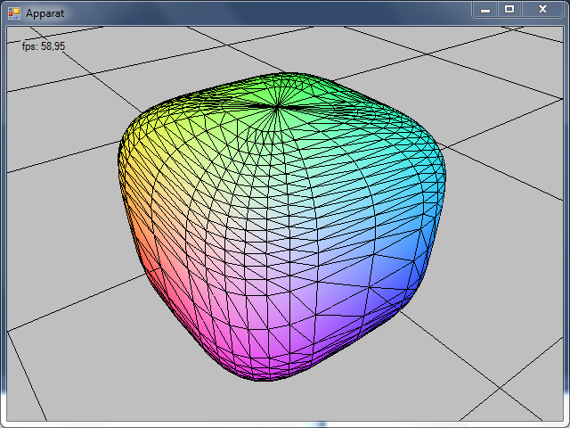
I will use the color cube as an example and this is what we are aiming at:


The cube consists of 8 vertices and each has a different color. Pixels that lie on the surface of the cube are being interpolated according to their position in the corresponding triangle.

I define the vertices of the cube, so that the center of the cube corresponds with the origin of its local coordinate system. Shorter: the center of the cube is (0,0,0).


In the center of the cube is the coordinate frame. A widely used color scheme is to map the axis to RGB color model: x-axis: red, y-axis: green, z-axis: blue. So what is up with those plusses and minusses? In order to keep the graphic clear, I omitted the values of the positions and depicted only the signs of the vector elements. Take a look at the x-axis: every vertex of the cube that lies in the positive x-axis, has a plus sign (all vertices on the right) and every vertex in the negative x-axis (all vertices on the left) have a negative sign.

And what is the purpose of this? If I have a negative sign at the position element (x,y or z), I set the corresponding color element (R,G or B) value to zero and if I have a positive sign, I set the color element to 255. This
is how I fill the vertex buffer and I colored the corresponding values green and red, to make this pattern more visible:


Now that we have set up the vertex buffer it is time to set up the index buffer. This picture depicts the order in which I have defined the vertices:


The sequence of vertex definitions is completely arbitrary, but once we have defined the vertices we need to stay consistent with this definition to get the triangles rendered in a right way. The default way DirectX handles triangle definition is by enumerating the vertices clockwise. If you are looking at a particular side, you have to enumerate the indices in the right order:


Look at the picture above and look at the case when looking straight at the top of the cube. We have indices 0,1,2 and 3. The triangulation I chose is: (0,1,2) and (2,3,0). This is also arbitrary as you also could  triangulate this side with (3,0,1) and (1,2,3). As long as you enumerate the indices in a clockwise order you get a valid triangulation.

I fill the index buffer corresponding to the picture above:

// Cube has 6 sides: top, bottom, left, right, front, back

// top
indices.WriteRange(new short[] { 0, 1, 2 });
indices.WriteRange(new short[] { 2, 3, 0 });

// right
indices.WriteRange(new short[] { 0, 5, 6 });
indices.WriteRange(new short[] { 6, 1, 0 });

// left
indices.WriteRange(new short[] { 2, 7, 4 });
indices.WriteRange(new short[] { 4, 3, 2 });

// front
indices.WriteRange(new short[] { 1, 6, 7 });
indices.WriteRange(new short[] { 7, 2, 1 });

// back
indices.WriteRange(new short[] { 3, 4, 5 });
indices.WriteRange(new short[] { 5, 0, 3 });

// bottom
indices.WriteRange(new short[] { 6, 5, 4 });
indices.WriteRange(new short[] { 4, 7, 6 });


Source Code

Putting everything together, this is the complete source code for the ColorCube Renderable:

using System;
using System.Collections.Generic;
using System.Linq;
using System.Text;
using System.Drawing;
using SlimDX.D3DCompiler;
using SlimDX;
using SlimDX.Direct3D11;
using SlimDX.DXGI;
using System.Runtime.InteropServices;

namespace Apparat.Renderables
{
    public class ColorCube : Renderable
    {
        ShaderSignature inputSignature;
        EffectTechnique technique;
        EffectPass pass;

        Effect effect;

        InputLayout layout;
        SlimDX.Direct3D11.Buffer vertexBuffer;
        SlimDX.Direct3D11.Buffer indexBuffer;
        DataStream vertices;
        DataStream indices;

        int vertexStride = 0;
        int numVertices = 0;
        int indexStride = 0;
        int numIndices = 0;

        int vertexBufferSizeInBytes = 0;
        int indexBufferSizeInBytes = 0;

        EffectMatrixVariable tmat;

        [StructLayout(LayoutKind.Sequential)]
        public struct Vertex
        {
            public Vector3 Position;
            public int Color;

            public Vertex(Vector3 position, int color)
            {
                this.Position = position;
                this.Color = color;
            }
        }

        public ColorCube()
        {
            try
            {
                using (ShaderBytecode effectByteCode = ShaderBytecode.CompileFromFile(
                    "Shaders/colorEffect.fx",
                    "Render",
                    "fx_5_0",
                    ShaderFlags.EnableStrictness,
                    EffectFlags.None))
                {
                    effect = new Effect(DeviceManager.Instance.device, effectByteCode);
                    technique = effect.GetTechniqueByIndex(0);
                    pass = technique.GetPassByIndex(0);
                    inputSignature = pass.Description.Signature;
                }
            }
            catch (Exception ex)
            {
                Console.WriteLine(ex.ToString());
            }

            var elements = new[] { 
                new InputElement("POSITION", 0, Format.R32G32B32_Float, 0),
                new InputElement("COLOR", 0, Format.B8G8R8A8_UNorm, 12, 0) 
            };
            layout = new InputLayout(DeviceManager.Instance.device, inputSignature, elements);


            tmat = effect.GetVariableByName("gWVP").AsMatrix();

            // half length of an edge
            float offset = 0.5f;

            vertexStride = Marshal.SizeOf(typeof(Vertex)); // 16 bytes
            numVertices = 8;
            vertexBufferSizeInBytes = vertexStride * numVertices;

            vertices = new DataStream(vertexBufferSizeInBytes, true, true);

            vertices.Write(new Vertex(new Vector3(+offset, +offset, +offset), Color.FromArgb(255, 255, 255).ToArgb())); // 0
            vertices.Write(new Vertex(new Vector3(+offset, +offset, -offset), Color.FromArgb(255, 255, 000).ToArgb())); // 1
            vertices.Write(new Vertex(new Vector3(-offset, +offset, -offset), Color.FromArgb(000, 255, 000).ToArgb())); // 2
            vertices.Write(new Vertex(new Vector3(-offset, +offset, +offset), Color.FromArgb(000, 255, 255).ToArgb())); // 3

            vertices.Write(new Vertex(new Vector3(-offset, -offset, +offset), Color.FromArgb(000, 000, 255).ToArgb())); // 4
            vertices.Write(new Vertex(new Vector3(+offset, -offset, +offset), Color.FromArgb(255, 000, 255).ToArgb())); // 5
            vertices.Write(new Vertex(new Vector3(+offset, -offset, -offset), Color.FromArgb(255, 000, 000).ToArgb())); // 6
            vertices.Write(new Vertex(new Vector3(-offset, -offset, -offset), Color.FromArgb(000, 000, 000).ToArgb())); // 7

            vertices.Position = 0;

            vertexBuffer = new SlimDX.Direct3D11.Buffer(
               DeviceManager.Instance.device,
               vertices,
               vertexBufferSizeInBytes,
               ResourceUsage.Default,
               BindFlags.VertexBuffer,
               CpuAccessFlags.None,
               ResourceOptionFlags.None,
               0);

            numIndices = 36;
            indexStride = Marshal.SizeOf(typeof(short)); // 2 bytes
            indexBufferSizeInBytes = numIndices * indexStride;

            indices = new DataStream(indexBufferSizeInBytes, true, true);

            // Cube has 6 sides: top, bottom, left, right, front, back

            // top
            indices.WriteRange(new short[] { 0, 1, 2 });
            indices.WriteRange(new short[] { 2, 3, 0 });

            // right
            indices.WriteRange(new short[] { 0, 5, 6 });
            indices.WriteRange(new short[] { 6, 1, 0 });

            // left
            indices.WriteRange(new short[] { 2, 7, 4 });
            indices.WriteRange(new short[] { 4, 3, 2 });

            // front
            indices.WriteRange(new short[] { 1, 6, 7 });
            indices.WriteRange(new short[] { 7, 2, 1 });

            // back
            indices.WriteRange(new short[] { 3, 4, 5 });
            indices.WriteRange(new short[] { 5, 0, 3 });

            // bottom
            indices.WriteRange(new short[] { 6, 5, 4 });
            indices.WriteRange(new short[] { 4, 7, 6 });

            indices.Position = 0;

            indexBuffer = new SlimDX.Direct3D11.Buffer(
                DeviceManager.Instance.device,
                indices,
                indexBufferSizeInBytes,
                ResourceUsage.Default,
                BindFlags.IndexBuffer,
                CpuAccessFlags.None,
                ResourceOptionFlags.None,
                0);

        }

        public override void render()
        {
            Matrix ViewPerspective = CameraManager.Instance.ViewPerspective;
            tmat.SetMatrix(ViewPerspective);

            DeviceManager.Instance.context.InputAssembler.InputLayout = layout;
            DeviceManager.Instance.context.InputAssembler.PrimitiveTopology = PrimitiveTopology.TriangleList;
            DeviceManager.Instance.context.InputAssembler.SetVertexBuffers(0, new VertexBufferBinding(vertexBuffer, vertexStride, 0));
            DeviceManager.Instance.context.InputAssembler.SetIndexBuffer(indexBuffer, Format.R16_UInt, 0);

            technique = effect.GetTechniqueByName("Render");

            EffectTechniqueDescription techDesc;
            techDesc = technique.Description;

            for (int p = 0; p < techDesc.PassCount; ++p)
            {
                technique.GetPassByIndex(p).Apply(DeviceManager.Instance.context);
                DeviceManager.Instance.context.DrawIndexed(numIndices, 0, 0);
            }
        }

        public override void dispose()
        {
            effect.Dispose();
            inputSignature.Dispose();
            vertexBuffer.Dispose();
            layout.Dispose();
        }
    }
}


Shader

Like I mentioned above, we also have to modify our shader in order to render the color of a vertex:

matrix gWVP;

struct VOut
{
    float4 position : SV_POSITION;
    float4 color : COLOR;
};

VOut VShader(float4 position : POSITION, float4 color : COLOR)
{
    VOut output;

    output.position = mul( position, gWVP);
    output.color = color;

    return output;
}

float4 PShader(float4 position : SV_POSITION, float4 color : COLOR) : SV_TARGET
{
    return color;
}

RasterizerState WireframeState
{
    FillMode = Wireframe;
    CullMode = None;
    FrontCounterClockwise = false;
};

technique10 Render
{
 pass P0
 {
  SetVertexShader( CompileShader( vs_4_0, VShader() ));
  SetGeometryShader( NULL );
  SetPixelShader( CompileShader( ps_4_0, PShader() ));
  //SetRasterizerState(WireframeState);
 }
}

Not much going on in the vertex shader VShader. The position of the vertex is multiplied with the WorldViewPerspective matrix from our camera to transform it to the right screen position and the color of the vertex is just handed through to the output of the shader.

Well, something is new. Take a look at the vertex shaders used in previous tutorials:

float4 VShader(float4 position : POSITION) : SV_POSITION
{
  return mul( position, gWVP);
}

This shader performed the above mentioned transformation from the local coordinate system of the model to the screen space and it returned a float4 structure.

Compare this to the new vertex shader. This has as output a new defined struct called VOut. To be able to hand down the color information of the vertex to the pixel shader, we need to have a structure, that also holds the color information.


Result

Now we can render vertices with color and get a nice color cube:


In the next tutorial I will show how to render a wireframe over this colored cube. If you download the code and play around with this example, you will notice that the grid will not be rendered over the cube even if it is in between the camera and the cube. This is because we haven't set up a depth buffer by now and this will be addressed in a further tutorial.


You can download the source code to this tutorial here.

Monday, April 15, 2013

GridMesh: Creating the IndexBuffer and Rendering as TriangleList

Introduction

This tutorial is one part of a series of tutorials about generating procedural meshes. See here for an outline.

We already created the vertices in the last tutorial. In order to triangulate the mesh, we need to create the index buffer, set it in the input assembler stage, change the primitive topology from point list to triangle list and change the draw call to draw indexed primitives.


VertexBuffer and IndexBuffer

There are two ways to draw triangles:

  1. explicitly listing every vertex of each triangle of a mesh
  2. having a list of vertices and describe each triangle by the indices in the vertex buffer
The first approach is useful for very small meshes like a rectangle. The second way is used to consume less memory for a mesh. Consider the size of a vertex with only the information for its position x,y,z: these are already three floats and you need to use 12 byte (as one float is 4 bytes). Having more complex vertices with position, color, normal, texture coordinates and what ever information you need for you shaders, the size of a  single vertex can grow significantly. In contrast to this, you need some sort of integer data type (byte (1), short (2), int (4), long (8) - with size in bytes in brackets) to point to an index in the vertex buffer.

Let's take a look at this rectangle, defined by four points p0, p1, p2 and p3:


Following the approach to explicitly list the vertices, we can triangulate the rectangle by creating a list of vertices: v0, v1, v2, v3 ,v4, v5

This results in the two triangles v0, v1, v2 (red) and v3, v4, v5 (blue):


Now we have a list of 6 vertices that have the according positions of the points. As you can see, we have to duplicate the positions p1 and p3 in our list of vertices. In this example I created the triangles clockwise by enumerating the vertices of a triangle in a clockwise manner (p0, p1, p3). In contrast to this the enumeration (p0, p3, p1) is counterclockwise. This list of 6 vertices would be our vertex buffer and we would tell the device to draw two triangles.

In order to avoid duplication of vertices when triangulating a mesh, we can use an index buffer. Again we need to set up a vertex buffer, but this holds this time just four vertices:

Vertex Buffer: v0, v1, v2, v3


Now, this picture does not look too much different from the picture above. Essential is the content of the index buffer, which points at the indices of the vertex buffer:


Now we can create the index buffer of the grid mesh.

Grid Mesh Source Code


using System;
using System.Collections.Generic;
using System.Linq;
using System.Text;
using SlimDX.D3DCompiler;
using SlimDX;
using SlimDX.Direct3D11;
using SlimDX.DXGI;

namespace Apparat.Renderables
{
    public class GridMesh2 : Renderable
    {
        SlimDX.Direct3D11.Buffer vertexBuffer;
        DataStream vertices;
        int numVertices = 0;

        SlimDX.Direct3D11.Buffer indexBuffer;
        DataStream indices;
        int numIndices = 0;

        InputLayout layout;

        
        int stride;

        ShaderSignature inputSignature;
        EffectTechnique technique;
        EffectPass pass;

        Effect effect;
        EffectMatrixVariable tmat;

        float stepSize;

        public GridMesh2(int witdh, int height, float stepSize)
        {
            int numVerticesWidth = witdh + 1;
            int numVerticesHeight = height + 1;

            this.stepSize = stepSize;

            numVertices = numVerticesWidth * numVerticesHeight;

            try
            {
                using (ShaderBytecode effectByteCode = ShaderBytecode.CompileFromFile(
                    "transformEffect.fx",
                    "Render",
                    "fx_5_0",
                    ShaderFlags.EnableStrictness,
                    EffectFlags.None))
                {
                    effect = new Effect(DeviceManager.Instance.device, effectByteCode);
                    technique = effect.GetTechniqueByIndex(0);
                    pass = technique.GetPassByIndex(0);
                    inputSignature = pass.Description.Signature;
                }
            }
            catch (Exception ex)
            {
                Console.WriteLine(ex.ToString());
            }

            tmat = effect.GetVariableByName("gWVP").AsMatrix();

            stride = 12;
            int sizeInBytes = stride * numVertices;
            vertices = new DataStream(sizeInBytes, true, true);

            float posX, posY;
            float startX = -witdh * stepSize / 2.0f;
            float startY = height * stepSize / 2.0f;

            for (int y = 0; y < numVerticesHeight; y++)
            {
                for (int x = 0; x < numVerticesWidth; x++)
                {
                    posX = startX + x * stepSize;
                    posY = startY - y * stepSize;

                    vertices.Write(new Vector3(posX, posY, 0));
                }
            }

            vertices.Position = 0;

            // create the vertex layout and buffer
            var elements = new[] { new InputElement("POSITION", 0, Format.R32G32B32_Float, 0) };
            layout = new InputLayout(DeviceManager.Instance.device, inputSignature, elements);
            vertexBuffer = new SlimDX.Direct3D11.Buffer(DeviceManager.Instance.device, vertices, sizeInBytes, ResourceUsage.Default, BindFlags.VertexBuffer, CpuAccessFlags.None, ResourceOptionFlags.None, 0);

            // create the index buffer
            int numPatches = (numVerticesWidth - 1) * (numVerticesHeight - 1);
            numIndices = numPatches * 6;
            indices = new DataStream(2 * numIndices, true, true);
         
            for (int y = 0; y < numVerticesHeight-1; y++)
            {
                for (int x = 0; x < numVerticesWidth-1; x++)
                {
                    short lu = (short)(x + (y * (numVerticesWidth)));
                    short ru = (short)((x + 1) + (y * (numVerticesWidth)));
                    short rb = (short)((x + 1) + ((y + 1) * (numVerticesWidth)));
                    short lb = (short)(x + ((y + 1) * (numVerticesWidth)));

                    // clockwise
                    indices.Write(lu);
                    indices.Write(ru);
                    indices.Write(lb);
                    

                    indices.Write(ru);
                    indices.Write(rb);
                    indices.Write(lb);
                }
            }

            indices.Position = 0;

            indexBuffer = new SlimDX.Direct3D11.Buffer(
                DeviceManager.Instance.device,
                indices,
                2 * numIndices,
                ResourceUsage.Default,
                BindFlags.IndexBuffer,
                CpuAccessFlags.None,
                ResourceOptionFlags.None,
                0);


        }

        public override void render()
        {
            Matrix ViewPerspective = CameraManager.Instance.ViewPerspective;
            tmat.SetMatrix(ViewPerspective);

            // configure the Input Assembler portion of the pipeline with the vertex data
            DeviceManager.Instance.context.InputAssembler.InputLayout = layout;
            DeviceManager.Instance.context.InputAssembler.PrimitiveTopology = PrimitiveTopology.TriangleList;
            DeviceManager.Instance.context.InputAssembler.SetVertexBuffers(0, new VertexBufferBinding(vertexBuffer, stride, 0));
            DeviceManager.Instance.context.InputAssembler.SetIndexBuffer(indexBuffer, Format.R16_UInt, 0);

            technique = effect.GetTechniqueByName("Render");

            EffectTechniqueDescription techDesc;
            techDesc = technique.Description;

            for (int p = 0; p < techDesc.PassCount; ++p)
            {
                technique.GetPassByIndex(p).Apply(DeviceManager.Instance.context);
                DeviceManager.Instance.context.DrawIndexed(numIndices, 0, 0);
            }
        }

        public override void dispose()
        {
        }
    }
}

Creating the IndexBuffer

As we created the vertex buffer with a double nested for loop, so we create the index buffer with a double nested for loop. To give you an intuition how I create the index buffer, take a look at this picture:

I start at vertex v0 and look at a patch of four vertices. Two from the current column (v0 and v1) and two from the next column (v5 and v6). From these four vertices I create two triangles by adding six indices to the index buffer. This way I iterate to vertex v3 and create the last two triangles for this column and then move to the next column and so on ...

SlimDX.Direct3D11.Buffer indexBuffer;
DataStream indices;
int numIndices = 0;


// create the index buffer
int numPatches = (numVerticesWidth - 1) * (numVerticesHeight - 1);
numIndices = numPatches * 6;
indices = new DataStream(2 * numIndices, true, true);

for (int y = 0; y < numVerticesHeight-1; y++)
{
  for (int x = 0; x < numVerticesWidth-1; x++)
  {
    short lu = (short)(x + (y * (numVerticesWidth)));
    short ru = (short)((x + 1) + (y * (numVerticesWidth)));
    short rb = (short)((x + 1) + ((y + 1) * (numVerticesWidth)));
    short lb = (short)(x + ((y + 1) * (numVerticesWidth)));

    // clockwise
    indices.Write(lu);
    indices.Write(ru);
    indices.Write(lb);
                    

    indices.Write(ru);
    indices.Write(rb);
    indices.Write(lb);
  }
}

indices.Position = 0;

indexBuffer = new SlimDX.Direct3D11.Buffer(
  DeviceManager.Instance.device,
  indices,
  2 * numIndices,
  ResourceUsage.Default,
  BindFlags.IndexBuffer,
  CpuAccessFlags.None,
  ResourceOptionFlags.None,
  0);


Let's compare the memory used for this approach and the example depicted in the picture above to the memory used for explicitly listing the vertices for triangulation:

The Explicit Case

We have 4 x 3 = 12 cells in the grid. Each cell consists of two triangles, so we get 12 x 2 = 24 triangles. For each triangle we need three vertices: 24 x 3 = 72 vertices. As we use the cheapest vertice type with position x,y,z only, one vertice costs 12 bytes. This results in 72 x 12 = 864 bytes.

Using an Index Buffer

We have 5 x 4 = 20 vertices, which cost 20 x 12 = 240 byte. As we still have to describe the triangles in the index buffer, we need 72 indices. We use shorts, so one index costs 2 bytes: 72 x 2 = 144 bytes. Summing the costs for vertex and index buffer, we get  240 + 144 = 384 bytes.

This effect of saving space for vertex data amplifies with the number of triangles one vertice is used for. The four vertices at the corner of the mesh are just used once for a triangle, the other vertices on the border of the grid are used twice for triangles and each vertice inside of the grid is used for four triangles. Some meshes have an even higher connectivity (meaning the use for triangles, for example on vertex is used for six triangles). 

Rendering the GridMesh

The next thing we have to adjust is the code in the render method. First we have to change the primitive typology to TriangleList. Next we have to set the index buffer with SetIndexBuffer. Finally we have to switch the Draw call to DrawIndexed. 

public override void render()
{
  Matrix ViewPerspective = CameraManager.Instance.ViewPerspective;
  tmat.SetMatrix(ViewPerspective);

  // configure the Input Assembler portion of the pipeline with the vertex data
  DeviceManager.Instance.context.InputAssembler.InputLayout = layout;
  DeviceManager.Instance.context.InputAssembler.PrimitiveTopology = PrimitiveTopology.TriangleList;
  DeviceManager.Instance.context.InputAssembler.SetVertexBuffers(0, new VertexBufferBinding(vertexBuffer, stride, 0));
  DeviceManager.Instance.context.InputAssembler.SetIndexBuffer(indexBuffer, Format.R16_UInt, 0);

  technique = effect.GetTechniqueByName("Render");

  EffectTechniqueDescription techDesc;
  techDesc = technique.Description;

  for (int p = 0; p < techDesc.PassCount; ++p)
  {
    technique.GetPassByIndex(p).Apply(DeviceManager.Instance.context);
    DeviceManager.Instance.context.DrawIndexed(numIndices, 0, 0);
  }
}

As a result we get a tessellated (triangulated) mesh:


Rendering as Wireframe

In order to see the triangulation of the mesh, we have to extend the shader with a RasterizerState. You can play around with FillMode, CullMode and FrontCounterClockwise to see what effects they have. 

See MSDN for the reference of the RasterizerState. Interesting are the default values for these states: FillMode (Solid), CullMode (Back) and FrontCouterClockwise (false). If you do not set the RasterizerState, Directx assumes, you want to fill your triangles, the front of your triangle is defined clockwise (like I did in my code above) and the back of the triangle will not be rendered.

matrix gWVP;

float4 VShader(float4 position : POSITION) : SV_POSITION
{
 return mul( position, gWVP);
}

float4 PShader(float4 position : SV_POSITION) : SV_Target
{
 return float4(0.0f, 1.0f, 0.0f, 1.0f);
}

RasterizerState WireframeState
{
    FillMode = Wireframe;
    //CullMode = Front;
    //FrontCounterClockwise = true;
};

technique10 Render
{
 pass P0
 {
  SetVertexShader( CompileShader( vs_4_0, VShader() ));
  SetGeometryShader( NULL );
  SetPixelShader( CompileShader( ps_4_0, PShader() ));
  SetRasterizerState(WireframeState);
 }
}


Using this shader, we get this wireframe of the grid mesh:


You can download the source code to this tutorial here.

Saturday, April 13, 2013

GridMesh: Creating the Vertex Buffer and Rendering as PointList

Grid Mesh

This tutorial is one part of a series of tutorials about generating procedural meshes. See here for an outline.

This tutorial deals with the creation of a vertex buffer for a mesh and rendering this mesh with the PointList primitive. We will start with a mesh for a rectangular grid of points. The grid extends along the x-axis and the y-axis and has three parameters:


  • width: number of cells in direction of the x-axis
  • height: number of cells in direction of the y-axis
  • cell size: length of each edge of a cell

A grid with the width of 4 and a height of 3 is shown in the following picture:
Grid with 4 Cells in x and 3 Cells in y.
In our coordinate system the x-axis goes to the right and the positive y-axis extends up.

Vertices

Vertices are the basis of meshes. Vertices can hold information about position, color, normals, texture coordinates and any other information you need for your shaders.
To keep things simple, we will start with vertices, that only have have a position. In order to create the mesh, we need a grid of vertices, as shown in the following picture:
Because one cell consists of 4 vertices, we need one more vertex for the width and height of the mesh, than we have cells. The 4 (width) x 3 (height) grid above needs therefore 5 vertices for each row and 4 vertices for each column of the mesh.

Iterative Creation of Vertices

How can we create such a mesh? One option is do define each vertex by hand. This is a valid approach, if you have simple objects like a cell made of two triangles that serves as a surface for a texture. For larger meshes and a flexible ways to create these (for example a grid with parameters for width and height) we need a different approach, which is called procedural mesh creation. A procedural mesh is created with a function that takes some parameters and computes the according mesh.

We start by filling the vertex buffer of the mesh. As we need a simple grid, we use a double nested for-loop to create the vertices iteratively.

We use the outer loop to iterate on the y value and the inner loop for the x value:

int width = 5;
int height = 4;

for (int y = 0; y < height; y++)
{
  for (int x = 0; x < width; x++)
  {
    Console.Write(y.ToString() + "," + x.ToString() + "\t");
  }
  Console.WriteLine();
}

This is the output on the console:


This gives us so far the indices of the positions. The first index is the row index (y) and the second index is the column index (x):
Vertices with Indices according to their position in row and column.

Because the VertexBuffer is not a matrix but an array, we need to linearize these indices, meaning, we have to match the indices in this matrix to an according array. We can do this by multiplying the y index of the outer loop with the width of the inner loop and adding the current x index to it:

int width = 5;
int height = 4;

for (int y = 0; y < height; y++)
{
  for (int x = 0; x < width; x++)
  {
    int index = x + y * width;
    Console.Write(index.ToString() + "\t");
  }
  Console.WriteLine();
}


We do not need to access the indices in this tutorial, but this will come in handy, when we have to triangulate the mesh.

Source Code

In this code of the grid mesh, I use the double nested for loop to create the vertices. Because it is convenient to place the center of the mesh in the origin of the coordinate system, I start in the upper left to write the vertices in the buffer. Also note, that I write the vertices from top to bottom, starting at the top row and going to the lowest row, by decreasing the y-position of the vertex:

float posX, posY;
float startX = -witdh * stepSize  / 2.0f;
float startY = height * stepSize  / 2.0f;
            

for (int y = 0; y < numVerticesHeight; y++)
{
  for (int x = 0; x < numVerticesWidth; x++)
  {
    posX = startX + x * stepSize;
    posY = startY - y * stepSize;

    vertices.Write( new Vector3(posX, posY, 0  ));
  }
}

The decision to iterate top down and from left to right is completely arbitrary but I think it is easier this way to imagine the access to the indices for further triangulation of the mesh.

This is the complete code of the grid:

using System;
using System.Collections.Generic;
using System.Linq;
using System.Text;
using SlimDX.D3DCompiler;
using SlimDX;
using SlimDX.Direct3D11;
using SlimDX.DXGI;

namespace Apparat.Renderables
{
    public class GridMesh : Renderable
    {
        SlimDX.Direct3D11.Buffer vertexBuffer;
        DataStream vertices;

        InputLayout layout;

        int numVertices = 0;
        int stride;

        ShaderSignature inputSignature;
        EffectTechnique technique;
        EffectPass pass;

        Effect effect;
        EffectMatrixVariable tmat;

        float stepSize;
        
        public GridMesh(int witdh, int height, float stepSize )
        {
            int numVerticesWidth = witdh + 1;
            int numVerticesHeight = height + 1;

            this.stepSize = stepSize;

            numVertices = numVerticesWidth * numVerticesHeight;

            try
            {
                using (ShaderBytecode effectByteCode = ShaderBytecode.CompileFromFile(
                    "transformEffect.fx",
                    "Render",
                    "fx_5_0",
                    ShaderFlags.EnableStrictness,
                    EffectFlags.None))
                {
                    effect = new Effect(DeviceManager.Instance.device, effectByteCode);
                    technique = effect.GetTechniqueByIndex(0);
                    pass = technique.GetPassByIndex(0);
                    inputSignature = pass.Description.Signature;
                }
            }
            catch (Exception ex)
            {
                Console.WriteLine(ex.ToString());
            }

            tmat = effect.GetVariableByName("gWVP").AsMatrix();

            stride = 12;
            int sizeInBytes = stride * numVertices;
            vertices = new DataStream(sizeInBytes, true, true);

            float posX, posY;
            float startX = -witdh * stepSize  / 2.0f;
            float startY = height * stepSize  / 2.0f;

            for (int y = 0; y < numVerticesHeight; y++)
            {
                for (int x = 0; x < numVerticesWidth; x++)
                {
                    posX = startX + x * stepSize;
                    posY = startY - y * stepSize;

                    vertices.Write( new Vector3(posX, posY, 0  ));
                }
            }

            vertices.Position = 0;

            // create the vertex layout and buffer
            var elements = new[] { new InputElement("POSITION", 0, Format.R32G32B32_Float, 0) };
            layout = new InputLayout(DeviceManager.Instance.device, inputSignature, elements);
            vertexBuffer = new SlimDX.Direct3D11.Buffer(DeviceManager.Instance.device, vertices, sizeInBytes, ResourceUsage.Default, BindFlags.VertexBuffer, CpuAccessFlags.None, ResourceOptionFlags.None, 0);
        }

        public override void render()
        {
            Matrix ViewPerspective = CameraManager.Instance.ViewPerspective;
            tmat.SetMatrix(ViewPerspective);

            // configure the Input Assembler portion of the pipeline with the vertex data
            DeviceManager.Instance.context.InputAssembler.InputLayout = layout;
            DeviceManager.Instance.context.InputAssembler.PrimitiveTopology = PrimitiveTopology.PointList;
            DeviceManager.Instance.context.InputAssembler.SetVertexBuffers(0, new VertexBufferBinding(vertexBuffer, stride, 0));
            
            technique = effect.GetTechniqueByName("Render");

            EffectTechniqueDescription techDesc;
            techDesc = technique.Description;

            for (int p = 0; p < techDesc.PassCount; ++p)
            {
                technique.GetPassByIndex(p).Apply(DeviceManager.Instance.context);
                DeviceManager.Instance.context.Draw(numVertices, 0);
            }
        }

        public override void dispose()
        {
        }
    }
}


Rendering

The only thing new at the render Method is, that I use the PointList primitive to render the points of the grid:

DeviceManager.Instance.context.InputAssembler.InputLayout = layout;
DeviceManager.Instance.context.InputAssembler.PrimitiveTopology = PrimitiveTopology.PointList;
DeviceManager.Instance.context.InputAssembler.SetVertexBuffers(0, new VertexBufferBinding(vertexBuffer, 12, 0));

Conclusion

In order to make the points of the grid more visible, I modified the pixel shader to paint green pixels and set the background to black. If you enlarge the picture, you might be able to see the green dots ;)


You can download the source code to this tutorial here.

Sunday, April 7, 2013

Outline: Procedural Meshes

In the next tutorials I will go into detail about vertices, vertex and index buffers and procedural mesh generation.

The first tutorial will be about procedural generation of vertices. For this I will use a simple grid mesh and we will render just the points of this grid.


The second tutorial will deal with creating an index buffer for the previous grid mesh and rendering the grid as a mesh of triangles. In order to view the mesh, we need to render the mesh as a wireframe and I will show you how to set the according state in a shader.


The third tutorial will be about bringing color to objects. For this we need to use different vertices and a new shader that is suited for displaying color.


The fourth tutorial will bring together wireframe rendering and color rendering. For this we modify our shader  to perform two passes.


The fifth tutorial will deal with the creation of the depth buffer and biased rendering to prevent z-fighting.


The next tutorials will show how to create the geometric primitives box, sphere, torus and cylinder with procedures.


Finally, I will close this series of tutorials with the geometric primitive of a superellipsoid, which is very versatile and fun to play around with. Here is a teaser, what will await you at the end of this series:


Saturday, March 30, 2013

Calculating Frames per Second

Motivation

One widely used metric to measure the performance of a render engine is frames per second. I will show you in this tutorial how to implement a class to perform this measurement.

FrameCounter Class

Source Code

using System;
using System.Collections.Generic;
using System.Linq;
using System.Text;
using System.Runtime.InteropServices;

namespace Apparat
{
    public class FrameCounter
    {
        [DllImport("Kernel32.dll")]
        private static extern bool QueryPerformanceCounter(
            out long lpPerformanceCount);

        [DllImport("Kernel32.dll")]
        private static extern bool QueryPerformanceFrequency(
            out long lpFrequency);

        #region Singleton Pattern
        private static FrameCounter instance = null;
        public static FrameCounter Instance
        {
            get
            {
                if (instance == null)
                {
                    instance = new FrameCounter();
                }
                return instance;
            }
        }
        #endregion

        #region Constructor
        private FrameCounter()
        {
            msPerTick = (float)MillisecondsPerTick;
        }
        #endregion

        float msPerTick = 0.0f;

        long frequency;
        public long Frequency
        {
            get
            {
                QueryPerformanceFrequency(out frequency);
                return frequency;
            }
        }

        long counter;
        public long Counter
        {
            get
            {
                QueryPerformanceCounter(out counter);
                return counter;
            }
        }

        public double MillisecondsPerTick
        {
            get
            {
                return (1000L) / (double)Frequency;
            }
        }

        public delegate void FPSCalculatedHandler(string fps);
        public event FPSCalculatedHandler FPSCalculatedEvent;

        long now;
        long last;
        long dc;
        float dt;
        float elapsedMilliseconds = 0.0f;
        int numFrames = 0;
        float msToTrigger = 1000.0f;

        public float Count()
        {
            last = now;
            now = Counter;
            dc = now - last;
            numFrames++;

            dt = dc * msPerTick;

            elapsedMilliseconds += dt;

            if (elapsedMilliseconds > msToTrigger)
            {
                float seconds = elapsedMilliseconds / 1000.0f;
                float fps = numFrames / seconds;

                if (FPSCalculatedEvent != null)
                    FPSCalculatedEvent("fps: " + fps.ToString("0.00"));
               
                elapsedMilliseconds = 0.0f;
                numFrames = 0;
            }

            return dt;
        }
    }
}

QueryPerformanceFrequency and QueryPerformanceCounter

To count the milliseconds during a render cycle, I use the two native methods QueryPerformanceFrequency and QueryPerformanceCounter. QueryPerformanceFrequency returns, how many ticks the high-resolution performance counter of your CPU makes in a second, you have to determine the frequency of your system just once because this value will not change on your system. QueryPerformanceCounter returns the number of current ticks of your system. To measure the number of ticks during a certain time span you have to get the number of ticks of your system at the beginning and the end of this time span and calculate the difference between the two.

Because you know how many ticks your system makes in a second, you can calculate the time span between the two measurements.

Count Function 

Let's have a look at the Count function in detail:

long now;
long last;
long dc;
float dt;
float elapsedMilliseconds = 0.0f;
int numFrames = 0;
float msToTrigger = 1000.0f;

public float Count()
{
  last = now;
  now = Counter;
  dc = now - last;
  numFrames++;

  dt = dc * msPerTick;

  elapsedMilliseconds += dt;

  if (elapsedMilliseconds > msToTrigger)
  {
    float seconds = elapsedMilliseconds / 1000.0f;
    float fps = numFrames / seconds;

    if (FPSCalculatedEvent != null)
      FPSCalculatedEvent("fps: " + fps.ToString("0.00"));
               
    elapsedMilliseconds = 0.0f;
    numFrames = 0;
  }

  return dt;
}

Every time this function gets called, I get the current value of the counter by calling the Counter Property. The previous value of the counter is assigned to the variable last and I calculate the difference dc of the two counter values, which is the number of ticks performed in the time span between two calls to this function. Because I calculated how many milliseconds it takes between two ticks (msPerTick), I can multiply dc with msPerTick to get the time span dt in milliseconds between two calls of this function.

The time span dt gets added to the variable elapsedMilliseconds. Furthermore I increment the variable numFrames with every call to the Count function. If elapsedMilliseconds is greater than the predefined time span msToTrigger, I calculate the frames per second fps and fire the  event FPSCalculatedEvent.

I call the Count function in every render cycle in the RenderManager:

FrameCounter fc = FrameCounter.Instance;

public void renderScene()
{
  while (true)
  {
    fc.Count();
               
    DeviceManager dm = DeviceManager.Instance;
    dm.context.ClearRenderTargetView(dm.renderTarget, new Color4(0.75f, 0.75f, 0.75f));

    Scene.Instance.render();

    dm.swapChain.Present(syncInterval, PresentFlags.None);
  }
}

FPSCalculatedEvent

I defined a delegate and an event in the FrameCounter class:

public delegate void FPSCalculatedHandler(string fps);
public event FPSCalculatedHandler FPSCalculatedEvent;

The event gets fired in the Count function, when the frames per secondes have been calculated. I'll get back to this delegate and event when it comes to presenting the fps on the RenderControl.

SyncInterval

Let's take a look at the render loop again:

public void renderScene()
{
  while (true)
  {
    fc.Count();
               
    DeviceManager dm = DeviceManager.Instance;
    dm.context.ClearRenderTargetView(dm.renderTarget, new Color4(0.75f, 0.75f, 0.75f));

    Scene.Instance.render();

    dm.swapChain.Present(syncInterval, PresentFlags.None);
  }
}

I introduced the variable syncInterval when calling the Present method of the swap chain.
The value of syncInterval determines, how the rendering is synchronized with the vertical blank.
If syncInterval  is 0, no synchronisation takes place, if syncInterval is 1,2,3 or 4, the frame is rendered after the nth interval (MSDN docs).

Furthermore I implemented a method to switch the syncInterval in the RenderManager externally:


int syncInterval = 1;

public void SwitchSyncInterval()
{
  if (syncInterval == 0)
  {
    syncInterval = 1;
  }
  else if (syncInterval == 1)
  {
    syncInterval = 0;
  }
}

This SwitchSyncInterval method is called in the RenderControl and you can switch the syncInterval with the F2 key:

private void RenderControl_KeyUp(object sender, KeyEventArgs e)
{
  if (e.KeyCode == Keys.F1)
  {
    CameraManager.Instance.CycleCameras();
  }
  else if (e.KeyCode == Keys.F2)
  {
    RenderManager.Instance.SwitchSyncInterval();
  }

  CameraManager.Instance.currentCamera.KeyUp(sender, e);
}

Displaying Frames per Second

I added a label control called DebugTextLabel to the RenderControl in order to display a string on top of the RenderControl to have a method to display text. Rendering text seems to be a bit more complicated with DirectX 11 than it was with DirectX 9. (If you know a good reference for rendering text in DirectX 11, please leave a comment). I will use this interim solution for displaying text until I wrote a parser for true type fonts ;)

The delegate and event for sending the calculated frames per second is defined in the FrameCounter class (see above) and the event is fired when the frames per second are calculated.

The method Instance_FPSCalculatedEvent in the class RenderControl is a handler for the FPSCalculatedEvent and is registered in the constructor of the RenderControl:

public RenderControl()
{
  InitializeComponent();
  this.MouseWheel += new MouseEventHandler(RenderControl_MouseWheel);
  FrameCounter.Instance.FPSCalculatedEvent += new FrameCounter.FPSCalculatedHandler(Instance_FPSCalculatedEvent);
}

This is the code for the handler Instance_FPSCalculatedEvent in the RenderControl:


delegate void setFPS(string fps);
void Instance_FPSCalculatedEvent(string fps)
{
  if (this.InvokeRequired)
  {
    setFPS d = new setFPS(Instance_FPSCalculatedEvent);
    this.Invoke(d, new object[] { fps });
  }
  else
  {
    this.DebugTextLabel.Text = fps;
  }
}

The label is set with the string fps, that comes as an argument from the event. Because the render loop works in a different thread than the DebugTextLabel was created in and we try to set this control from the render loop thread, we have to use the InvokeRequired property of the RenderControl.

Results

Now we can display the current frame rate of the render engine:

~60 Frames per Second with SyncInterval = 1

Several thousand Frames per Second with SyncInterval = 0

To play around a bit, insert a Thread.Sleep(ms)statement to the method renderScene in the RenderManager class and observe how the frame rate changes with different values for ms and depending on if you use syncInterval = 1 or syncInterval = 0. Also try to set the syncInterval in the render loop to values of 2,3,4 and observe the effect on the frames per second.

The source code to this tutorial is here.

Have fun!

Sunday, March 24, 2013

The Ego Camera

With an Ego Camera you use the mouse to control the pitch and yaw of the camera and the WSAD keys to move forward and backward and strafe left and right. I constrain the pitch of the camera at +90 and -90 degree.

Abstract Camera Class


using System;
using System.Collections.Generic;
using System.Linq;
using System.Text;
using System.Windows.Forms;
using SlimDX;

namespace Apparat
{
    public abstract class Camera
    {
        public Vector3 eye;
        public Vector3 target;
        public Vector3 up;

        public Matrix view = Matrix.Identity;
        public Matrix perspective = Matrix.Identity;
        public Matrix viewPerspective = Matrix.Identity;

        public Matrix View
        {
            get { return view; }
        }

        public void setPerspective(float fov, float aspect, float znear, float zfar)
        {
            perspective = Matrix.PerspectiveFovLH(fov, aspect, znear, zfar);
        }

        public void setView(Vector3 eye, Vector3 target, Vector3 up)
        {
            view = Matrix.LookAtLH(eye, target, up);
        }

        public Matrix Perspective
        {
            get { return perspective; }
        }

        public Matrix ViewPerspective
        {
            get { return view * perspective; }
        }

        public bool dragging = false;
        public int startX = 0;
        public int deltaX = 0;

        public int startY = 0;
        public int deltaY = 0;

        public abstract void MouseUp(object sender, MouseEventArgs e);
        public abstract void MouseDown(object sender, MouseEventArgs e);
        public abstract void MouseMove(object sender, MouseEventArgs e);
        public abstract void MouseWheel(object sender, MouseEventArgs e);

        public abstract void KeyPress(object sender, KeyPressEventArgs e);
        public abstract void KeyDown(object sender, KeyEventArgs e);
        public abstract void KeyUp(object sender, KeyEventArgs e);
    }
}

Because we need the WSAD keys for strafing, the abstract class needs the declaration of the handlers for handling input from keys. These have also to be implemented in the OrbitCamera and in the OrbitPanCamera, but remain empty.

Ego Camera Code


using System;
using System.Collections.Generic;
using System.Linq;
using System.Text;
using SlimDX;
using SlimDX.Direct3D11;
using SlimDX.DXGI;

namespace Apparat
{
    public class EgoCamera : Camera
    {
        Vector3 look;

        public EgoCamera()
        {
            look = new Vector3(1, 0, 0);
            up = new Vector3(0, 1, 0);
            eye = new Vector3(0, 1, 0);
            target = eye + look;

            view = Matrix.LookAtLH(eye, target, up);
            perspective = Matrix.PerspectiveFovLH((float)Math.PI / 4, 1.3f, 0.0f, 1.0f);
        }

        new public Matrix  ViewPerspective
        {
            get
            {
                if (strafingLeft)
                    strafe(1);

                if (strafingRight)
                    strafe(-1);

                if (movingForward)
                    move(1);

                if (movingBack)
                    move(-1);
                
                return view * perspective;
            }
        }

        public void yaw(int x)
        {
            Matrix rot = Matrix.RotationY(x / 100.0f);
            look = Vector3.TransformCoordinate(look, rot);

            target = eye + look;
            view = Matrix.LookAtLH(eye, target, up);
        }


        float pitchVal = 0.0f;
        public void pitch(int y)
        {
            Vector3 axis = Vector3.Cross(up, look);
            float rotation = y / 100.0f;
            pitchVal = pitchVal + rotation;

            float halfPi = (float)Math.PI / 2.0f;

            if (pitchVal < -halfPi)
            {
                pitchVal = -halfPi;
                rotation = 0;
            }
            if (pitchVal > halfPi)
            {
                pitchVal = halfPi;
                rotation = 0;
            }

            Matrix rot = Matrix.RotationAxis(axis, rotation);

            look = Vector3.TransformCoordinate(look, rot);
            
            look.Normalize();
            
            target = eye + look;
            view = Matrix.LookAtLH(eye, target, up);
        }

        public override void MouseUp(object sender, System.Windows.Forms.MouseEventArgs e)
        {
            dragging = false;
        }

        public override void MouseDown(object sender, System.Windows.Forms.MouseEventArgs e)
        {
            dragging = true;
            startX = e.X;
            startY = e.Y;
        }

        public override void MouseMove(object sender, System.Windows.Forms.MouseEventArgs e)
        {
            if (dragging)
            {
                int currentX = e.X;
                deltaX = startX - currentX;
                startX = currentX;

                int currentY = e.Y;
                deltaY = startY - currentY;
                startY = currentY;

                if (e.Button == System.Windows.Forms.MouseButtons.Left)
                {
                    pitch(deltaY);
                    yaw(-deltaX);
                }
            }
        }

        public void strafe(int val)
        {
            Vector3 axis = Vector3.Cross(look, up);
            Matrix scale = Matrix.Scaling(0.1f, 0.1f, 0.1f);
            axis = Vector3.TransformCoordinate(axis, scale);

            if (val > 0)
            {
                eye = eye + axis;
            }
            else
            {
                eye = eye - axis;
            }
            
            target = eye + look;
            view = Matrix.LookAtLH(eye, target, up);
        }

        public void move(int val)
        {
            Vector3 tempLook = look;
            Matrix scale = Matrix.Scaling(0.1f, 0.1f, 0.1f);
            tempLook = Vector3.TransformCoordinate(tempLook, scale);


            if (val > 0)
            {
                eye = eye + tempLook;
            }
            else
            {
                eye = eye - tempLook;
            }
            
            target = eye + look;
            view = Matrix.LookAtLH(eye, target, up);
        }

        // Nothing to do here
        public override void MouseWheel(object sender, System.Windows.Forms.MouseEventArgs e){}


        public override void KeyPress(object sender, System.Windows.Forms.KeyPressEventArgs e)
        {
        }

        bool strafingLeft = false;
        bool strafingRight = false;
        bool movingForward = false;
        bool movingBack = false;

        public override void KeyDown(object sender, System.Windows.Forms.KeyEventArgs e)
        {
            if (e.KeyCode == System.Windows.Forms.Keys.W)
            {
                movingForward = true;
            }
            else if (e.KeyCode == System.Windows.Forms.Keys.S)
            {
                movingBack = true;
            }
            else if (e.KeyCode == System.Windows.Forms.Keys.A)
            {
                strafingLeft = true;
            }
            else if (e.KeyCode == System.Windows.Forms.Keys.D)
            {
                strafingRight = true;
            }
        }

        public override void KeyUp(object sender, System.Windows.Forms.KeyEventArgs e)
        {
            if (e.KeyCode == System.Windows.Forms.Keys.W)
            {
                movingForward = false;
            }
            else if (e.KeyCode == System.Windows.Forms.Keys.S)
            {
                movingBack = false;
            }
            else if (e.KeyCode == System.Windows.Forms.Keys.A)
            {
                strafingLeft = false;
            }
            else if (e.KeyCode == System.Windows.Forms.Keys.D)
            {
                strafingRight = false;
            }
        }
    }
}

Key Handling

In the lowest section of the code I implemented four booleans in order to flag, if a key keeps being pressed. As long as a key is pressed, these variables stay true. You may wonder, why I don't use the KeyPress handler for this. As soon as a key is pressed, the KeyPress event is fired and the KeyPress handler is called. If the key remains pressed, the event is fired repeatedly and the therefore the handler is called repeatedly. The problem is: this event is fired once a key is pressed, followed by a pause and then the event is fired at a low frequency at about 15 Hz (roughly estimated, I haven't found any reference).

This video illustrates the issue:

I opened notepad and kept the 'a' key pressed. After a short pause, the events keeps being fired at a low frequency.

As the Render Loop works with 60Hz or more, using the KeyPress event would result in a stuttering motion of the camera, if used for triggering the strafing methods, as the ViewProjection matrix of the camera would only be fired every fourth frame  (again, roughly estimated).

The ViewPerspective Property

Also observe, that I overrode the ViewPerspective property. The objects in the scene call this property in every render cycle, in order to make sure, that these objects get a updated ViewPerspective matrix, the update of the strafing methods happens here.

Warning: this is not a good implementation and only to prevent the camera from stuttering in this tutorial. The problem with the current approach is, that the objects in the scene trigger a transformation by using this property. So every call to this property results in a transformation of the camera. Having many objects would give noticeable effects on the displayed scene. In a later tutorial the call to ViewPerspective matrix will be moved into the beginning of the render loop and called once and the objects in the scene will all see the same ViewPerspective matrix. This approach has also the advantage, that expensive calculations will be only performed once per render loop.

Strafing

Strafing is a translation along the cameras x-axis and z.axis. Up to now we just used the eye, target and up vectors for creating the view matrix of the camera. In order to do implement strafing, I need two additional vectors: look and axis. look is the direction the camera is looking in and axis is orthogonal to up and look
Strafing forward and backward is then adding a scaled look vector to the eye vector. Strafing left and right is accomplished by adding a scaled axis vector to the eye vector. To keep the creation of the view matrix consistent, the target vector has to be updated with the same vector as the eye vector.

Looking

To look around, I take the look vector and rotate this vector around the cameras y axis for looking left and right. In order to look up and down the look vector is rotated around the cameras z axis. The y axis is always the up vector, which isn't touched at all and is (0,1,0) at all times. Because the camera is rotating, the current z axis of the camera has to be recomputed, with every rotation around the y axis. The cameras current z axis (just called axis in the source code) is therefore computed by taking the cross product of the up vector and the look vector.
To constrain looking up and down, the pitch angle is limited to +PI/2 and -PI/2.

Camera Manager


using System;
using System.Collections.Generic;
using System.Linq;
using System.Text;
using SlimDX;

namespace Apparat
{
    public class CameraManager
    {
        #region Singleton Pattern
        private static CameraManager instance = null;
        public static CameraManager Instance
        {
            get
            {
                if (instance == null)
                {
                    instance = new CameraManager();
                }
                return instance;
            }
        }
        #endregion

        #region Constructor
        private CameraManager() 
        {
            OrbitPanCamera ocp = new OrbitPanCamera();
            OrbitCamera oc = new OrbitCamera();
            EgoCamera ec = new EgoCamera();
            cameras.Add(ocp);
            cameras.Add(oc);
            cameras.Add(ec);

            currentIndex = 0;
            currentCamera = cameras[currentIndex];
        }
        #endregion

        List<camera> cameras = new List<camera>();

        public Camera currentCamera;
        int currentIndex;

        public Matrix ViewPerspective
        {
            get
            {
                if (currentCamera is EgoCamera)
                {
                    return ((EgoCamera)currentCamera).ViewPerspective;
                }
                else
                {
                    return currentCamera.ViewPerspective;
                }
            
            }
        }

        public string CycleCameras()
        {
            int numCameras = cameras.Count;
            currentIndex = currentIndex + 1;
            if (currentIndex == numCameras)
                currentIndex = 0;
            currentCamera = cameras[currentIndex];
            return currentCamera.ToString();
        }
    }
}

The EgoCamera is added to the camera manager by creating an object of it and adding it to the cameras list. I had to add the ViewPerspective property, to be able to cast the current camera to the EgoCamera if the current camera is of this type. This is necessary to call the ViewPerspective property of the EgoCamera, because I did override the ViewPerspective property of the abstract Camera class in the EgoCamera.

Results

This video demonstrates the behaviour of the Ego Camera:


At this point I am using constants for the translations and rotations. In order to have defined velocities for these motions, we need to know, how much time has passed. This will be addressed in the next tutorial.

You can download the source code of this tutorial here.